
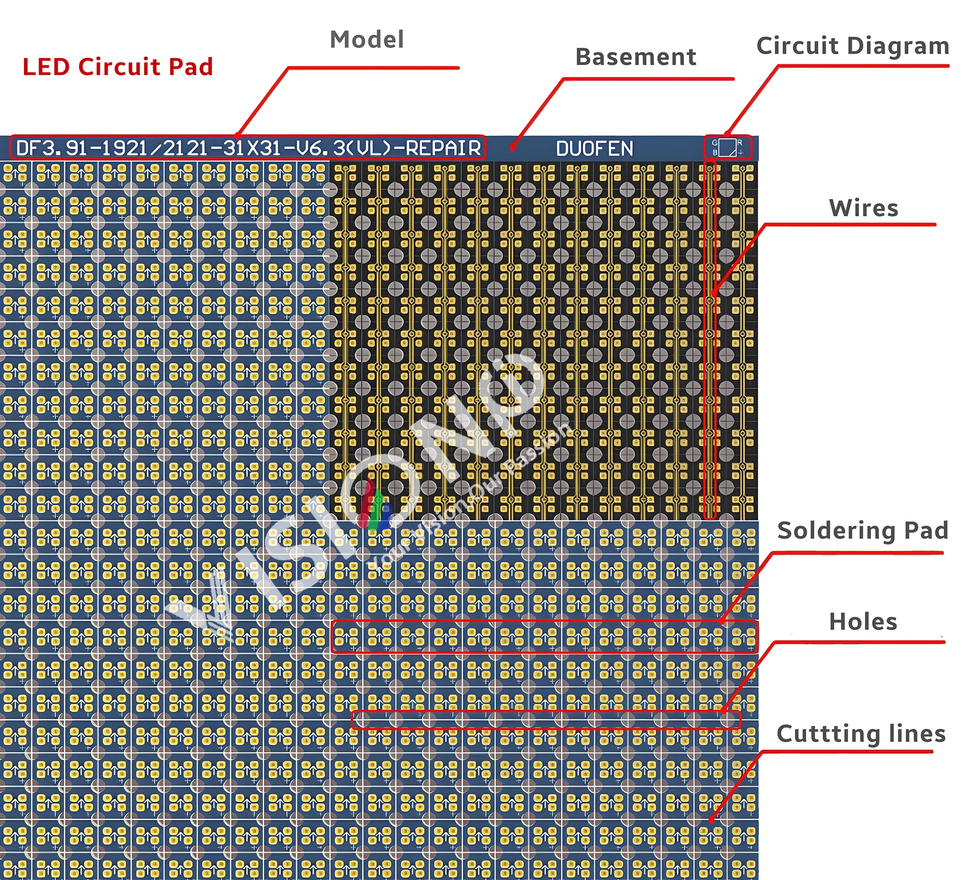
Circuit paper, a specialized double-layer flexible circuit board with a thickness ranging from 0.08 to 0.1 mm, is essential for repairing damaged PCB pads in LED modules. Its components include screen printing, base material, pads, holes, wires, and cutting lines. During installation, disassembly, or transportation, LED displays may suffer collisions leading to PCB pad detachments. In such scenarios, circuit paper serves as an effective repair solution.
Selecting Appropriate Circuit Paper for your LED Modules
To ensure compatibility and functionality, consider the following factors when choosing circuit paper:
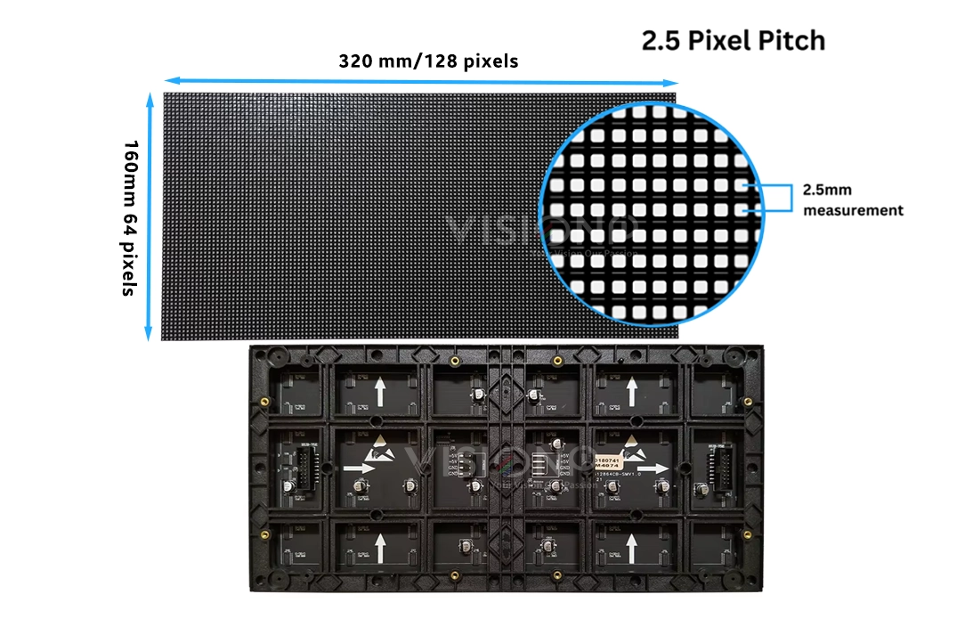
- Pixel Pitch Consistency: The pixel pitch of the circuit paper must match that of the original LED module. Pixel pitch refers to the distance between the centers of two adjacent pixels, typically measured in millimeters. A consistent pixel pitch ensures uniformity in display resolution and image quality. citeturn0search8
- LED Bead Specifications: Align the specifications of the LED beads on the circuit paper with those on the original module. This alignment is crucial for maintaining consistent brightness, color, and overall visual performance.
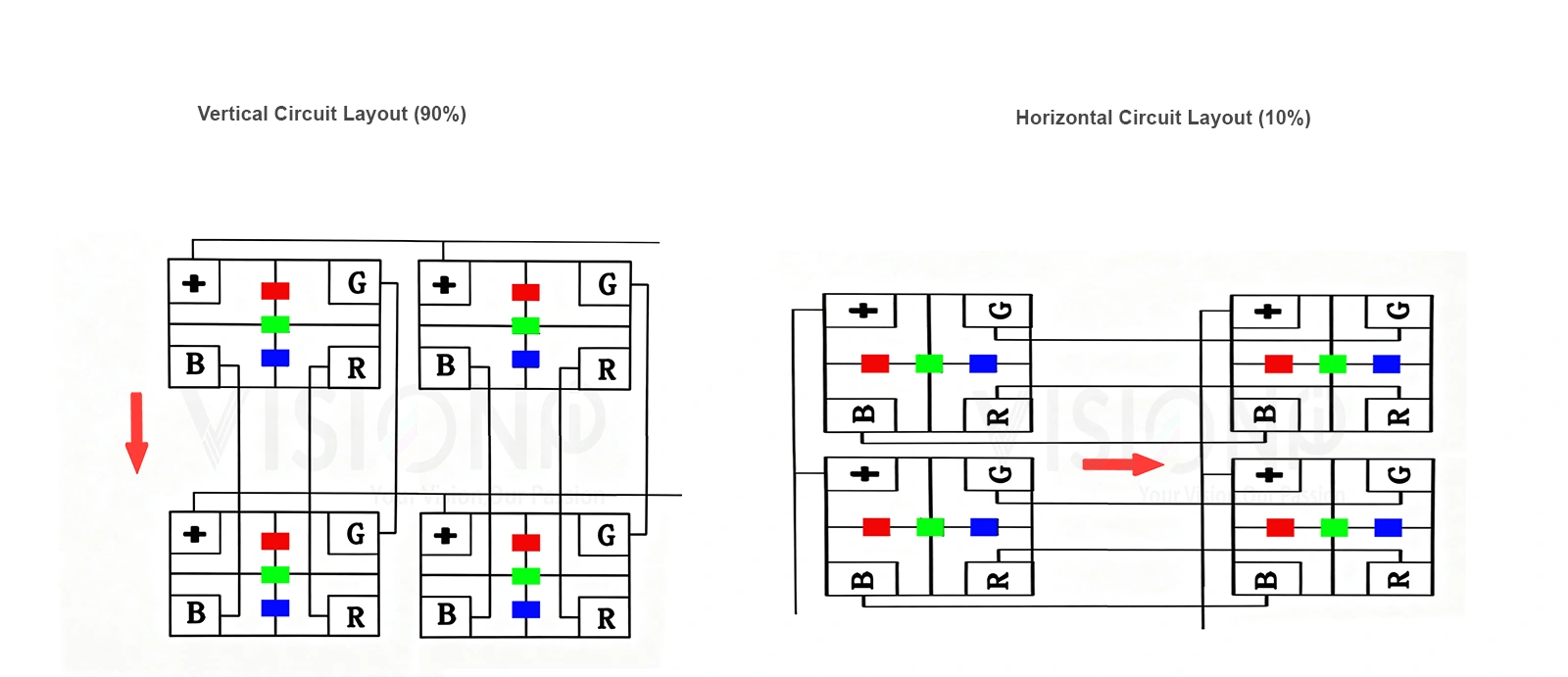
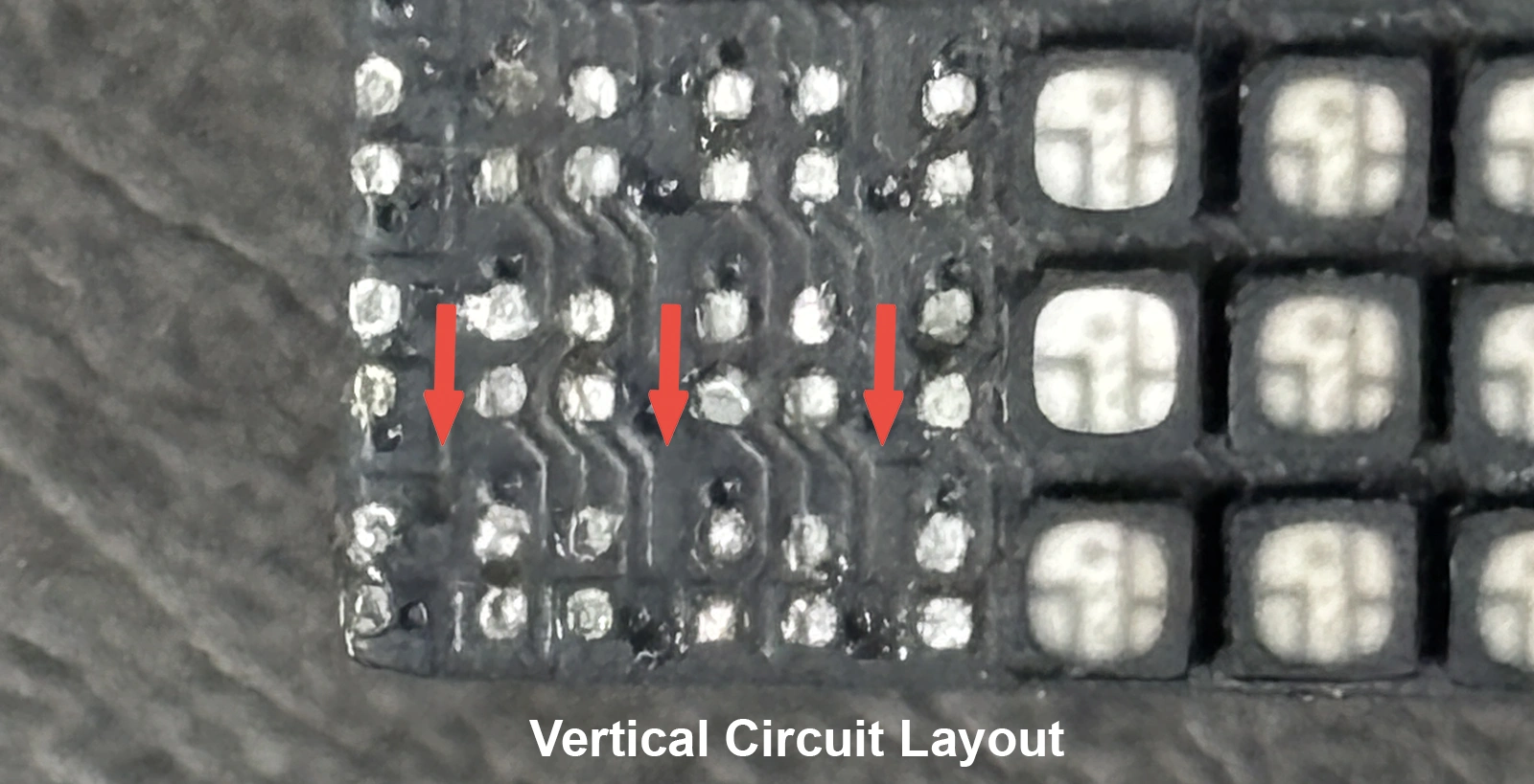
- Lamp Orientation: LED modules can feature vertical or horizontal lamp orientations, with vertical lamps being more prevalent. It’s imperative to select circuit paper that matches the lamp orientation of the original module to ensure proper alignment and functionality.
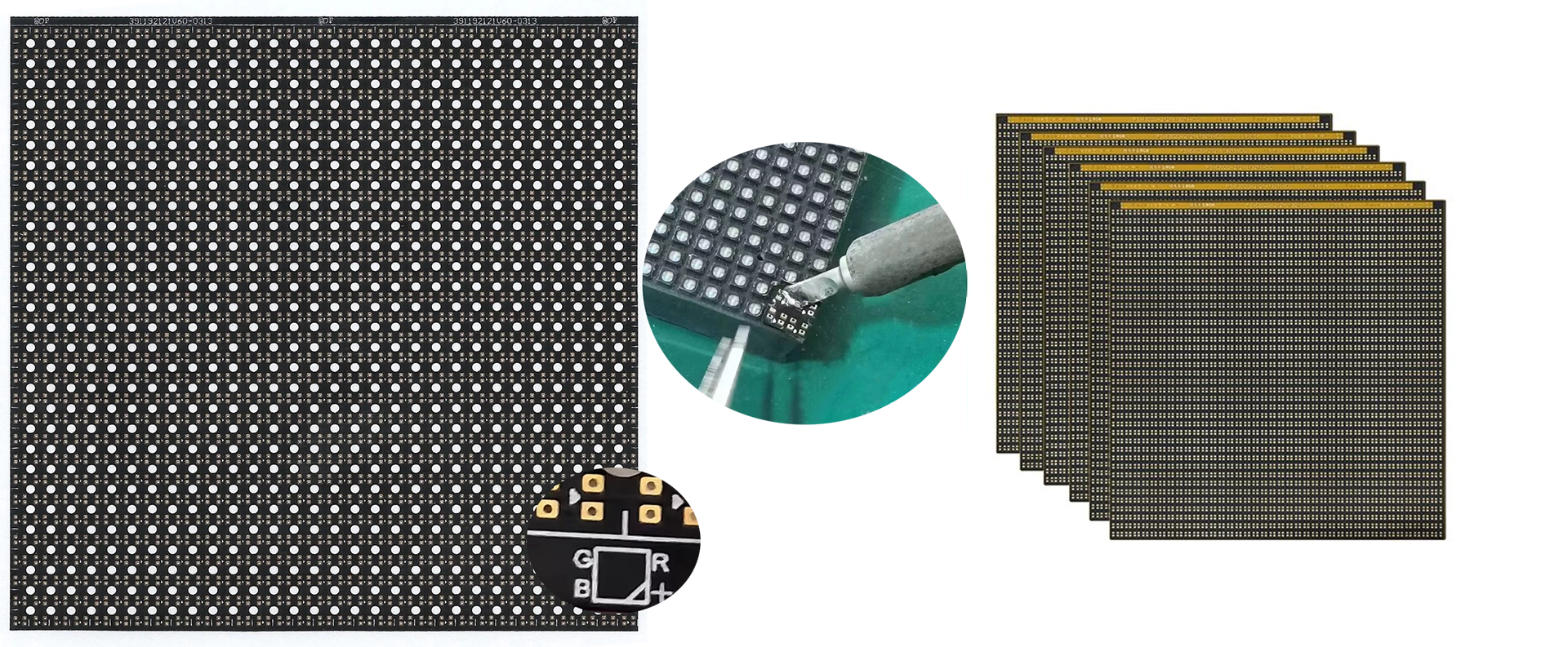
Measuring LED Module Pixel Pitch
Accurate measurement of the pixel pitch is vital for selecting compatible circuit paper. Follow these steps:
- Measure Module Width (W): Using a caliper, determine the horizontal dimension of the LED module.
- Count Horizontal LED Beads (N): Tally the number of LED lamp beads along the horizontal axis.
- Calculate Pixel Pitch (P): Apply the formula P = W / N to compute the pixel pitch. Ensure numerical accuracy to three decimal places for precision.
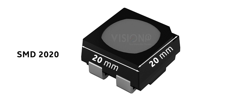
Determining LED Bead Specifications
To identify the size of surface-mount device (SMD) LED beads:
- Measure Horizontal Dimension (X): Use a caliper to measure the LED bead’s width.
- Measure Vertical Dimension (Y): Similarly, measure the LED bead’s height.
- Specify LED Bead Size: Document the specifications as SMD (X×Y), indicating the precise dimensions.
Differentiating Vertical and Horizontal Lamps
Understanding the distinction between vertical and horizontal lamps is essential for proper circuit paper selection. Vertical lamps are more commonly used and have specific structural orientations compared to horizontal lamps. Choosing circuit paper that matches the lamp orientation of the original module ensures seamless integration and optimal performance.
Application of Circuit Paper
To effectively use circuit paper in repairing PCB pads:
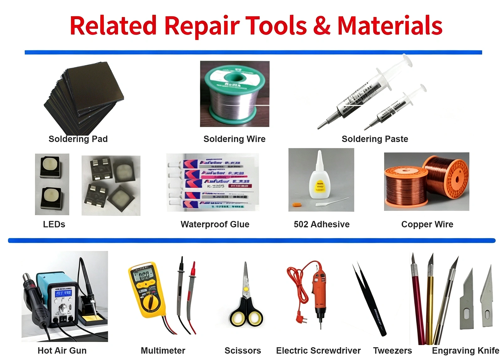
- Prepare Tools and Materials: Gather necessary items such as an anti-static bracelet, soldering iron, hot air gun, multimeter, tweezers, tin wire, solder paste, scissors, screwdriver, LED beads, circuit paper, and integrated circuits (ICs).
- Clean the Damaged Pad: Gently scrape the damaged PCB pad with a blade and clean it with alcohol to prevent potential short circuits when applying the circuit paper.
- Cut and Tin the Circuit Paper: Trim the circuit paper to the required size and apply a thin layer of tin to both sides of the pad. This step ensures a secure connection without causing short circuits due to excessive tin.
- Attach the Circuit Paper: Set the soldering iron to approximately 320°C. Using tweezers, position the tinned circuit paper over the PCB pad, ensuring correct alignment of common poles. Gently press and heat with the soldering iron or hot air gun to fuse the circuit paper with the PCB pad.
- Test and Solder LED Beads: Power the module, display a full white screen, and adjust brightness to a comfortable level. Solder the appropriate LED beads onto the circuit paper, ensuring correct polarity. Use a multimeter to verify proper connections before finalizing the soldering.
- Finalize the Repair: After successful testing, apply glue to the repaired area to secure the LED beads. Note that indoor modules may not require glue filling.
By meticulously following these guidelines, technicians can ensure precise repairs of LED display PCB pads, maintaining the display’s integrity and performance.
How to Repair Lifted Solder Pads on Outdoor LED Modules Using Solder‑Pad Repair Paper
Step 1: Remove LED beads from the damaged pad area
Based on the scope of lifted or damaged solder pads, desolder and remove all LED lamp beads that sit above the faulty PCB pads. This clears space to work on the underlying PCB surface.
Step 2: Clean up waterproof compound, traces, and burrs.
Remove all original waterproof glue from the repair zone. Clear residual burrs and damaged circuit traces. For traces that have partially lifted but are not fully broken, cut them cleanly with an engraving knife. This eliminates hidden short‑circuit risks before applying repair paper.
Step 3: Secure solder‑pad repair paper and match polarity.
Fix the repair paper onto the PCB. Locate the positive pin position for the LED lamp bead. Align the positive polarity of the cut repair paper exactly with the positive pad position on the original module. Hold it steady and tack it down using a soldering iron. Make sure there is no offset or shifting after fixing.
Step 4: Tin the rebuilt pads, power‑on inspection
Once the repair paper is secured without shifting, run the soldering‑iron tip across the pads on the repair paper to quickly tin and level them. After tinning, power up the module and run a continuity test. Inspect for short circuits, cold solder joints, or any misalignment of the repair paper. Only proceed to re‑mount lamp beads after confirming no electrical faults. Recommendation: Use standard 63/37 tin‑lead solder wire for this rework process.
Step 5: Re‑install LED beads with a hot‑air gun, re‑apply waterproof compound
Re‑fit each LED lamp bead using a hot‑air gun. Keep the module powered on and displaying a full‑white test pattern during bead replacement. Set the hot-air gun temperature between 260 °C and 300 °C. Apply a small amount of solder paste or flux to each pad before placing lamp beads; flux improves soldering quality. After soldering all lamp beads, restore the surface with waterproof glue.
Important practical notes for outdoor LED modules
Choose your rework tool according to the pixel pitch of your outdoor LED module:
- Larger pixel‑pitch outdoor modules: hot‑air gun rework works fine.
- Fine‑pitch modules such as P3 and below: Hot‑air rework is generally not suitable; soldering‑iron replacement is preferred.
Need Precision Soldering Pads for LED Displays?
Ensure flawless connections with industry-grade soldering pads: Chat with Our PCB Engineers Now! WhatsApp Us