Solar Power LED Screen

The LED display we are introducing marks a significant advancement in renewable energy utilization and energy-efficient technology. This state-of-the-art display is powered entirely by solar energy, harnessing the sustainable power of the sun to operate with unparalleled efficiency. At the heart of this system lies our newly developed energy storage module, a testament to our commitment to innovation in the field of green technology.

SOLAR LED DISPLAY copy

What are solar powered LED display?

Solar-powered LED displays are electronic devices that use light-emitting diodes (LEDs) to show images, text, or videos. LEDs are small semiconductor components that emit light when an electric current passes through them. They are more energy-efficient, durable, and versatile than traditional incandescent or fluorescent bulbs.

Solar-powered LED displays use photovoltaic (PV) panels to convert sunlight into electricity, which is then stored in batteries or capacitors. The stored electricity is used to power the LEDs and other components of the display, such as controllers, sensors, or speakers. Some solar-powered LED displays also have backup power sources, such as grid connections or generators, to ensure continuous operation in low-light or cloudy conditions.

How do solar-powered LED displays work?

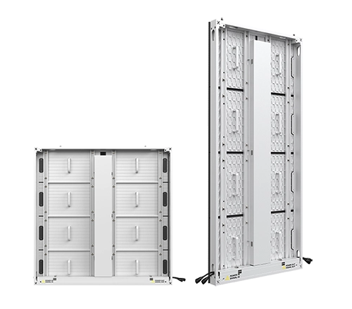
A solar-powered LED display consists of three parts: the solar control part, the battery part, and the LED display part. The solar control part is responsible for measuring the solar voltage, controlling the battery charging and discharging, and regulating the output voltage. The battery part stores the electrical energy converted from the solar panel. The LED display part shows the dynamic information from the video signal.

The solar controller is the key component of the system, as it affects the performance and service life of the battery and the LED display. The solar controller monitors the battery charge and discharge conditions and prevents overcharge or deep discharge. The solar controller also adjusts the output voltage according to the load demand and protects the system from short circuits or overloads.

The design of the solar controller includes the following aspects: solar voltage measurement, battery charging and discharging control, output voltage regulation, and system protection

solar powered led screen working principle
HOW SOLAR POWER LED SIGN WORKS

This cutting-edge module is designed to accumulate and store solar energy with exceptional efficiency, ensuring a reliable power supply to the LED display for over 32 hours in conditions devoid of sunlight. Such capability is pivotal for continuous operation, particularly in geographic areas with varying sunlight availability. The module’s sophisticated design enables it to charge during daylight hours while simultaneously powering the display, a feature we describe as “charging and playing synchronization.” This ensures that the display remains operational, showcasing vivid and dynamic content without interruption, regardless of the solar conditions.

solar power panel for led display copy

What are the benefits of solar-powered LED displays?

Solar-powered LED displays have many advantages over conventional displays that rely on grid electricity or fossil fuels. Some of the benefits are:

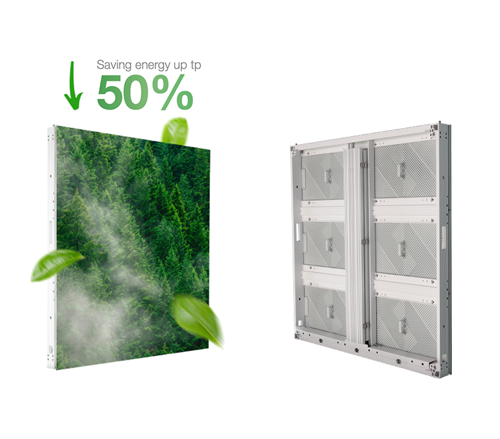
  • Environmentally friendly

    . Solar-powered LED displays reduce greenhouse gas emissions and air pollution by using renewable energy sources instead of fossil fuels. They also reduce waste and resource consumption by having longer lifespans and lower maintenance costs than traditional displays.

  • Cost-effective

    . Solar-powered LED displays have lower operating costs than conventional displays because they do not need to pay for electricity bills or fuel costs. They also have lower installation costs because they do not need complex wiring or infrastructure. They can pay for themselves in a few years by saving on energy expenses.

  • Unlimited Flexibility in Install Location

    Solar-powered LED displays can be used for various applications, such as advertising, education, entertainment, information, security, or art. They can be installed in any location that receives adequate sunlight, such as rooftops, walls, windows, billboards, vehicles, or portable stands. They can also be customized in different shapes, sizes, colors, and resolutions to suit different needs and preferences.

  • Reliable

    . Solar-powered LED displays can operate independently of the grid or other power sources, which makes them ideal for remote areas or emergency situations. They can also withstand harsh weather conditions and extreme temperatures better than conventional displays because they have no moving parts or fragile components. 

Visionpi-Solar LED Poster Display

1. Realize solar power and utility power interchange function
2. Adjustable brightness, which can meet the needs of various environments
3. Cloud control, 4G, tablet wireless connection, video, picture, and text multiple interactions
4. Energy storage power display, ultra-long playback
5. Minimal installation, the front maintenance led panel can be directly removed from the front.
6. Synchronized audio and video output
7. Realize 100% electricity-free, solve the practical problem of difficult-to-pull electricity, and high wiring costs.
8. Waterproof grade up to IP65.

Solar Power LED Display Applications

All countries of the world have adopted sustainable energy development strategies to protect the environment and ecology while using energy resources. Solar energy is a key area of development planning as a new energy industry. Solar photovoltaic is one of the fastest growing industries in the world, with an average annual growth rate of 40% in the last five years, surpassing the IT industry. As a clean and renewable energy source, solar energy generation is one of the most important directions for the world’s new energy development. The solar energy generation industry is rapidly emerging.


Electronic displays are widely used in various fields to show dynamic information. They can work both indoors and outdoors, and have many advantages over other display media. They can display text, images, and animations directly from video signals. Solar energy can power electronic displays, making them ideal for remote and inconvenient locations. Remote control can make them more convenient and timely. Solar energy also saves energy and protects the environment. This paper will design a solar-powered LED display based on the principle of electronic display screen.

SOLAR POWER LED POSTER DISPLAY copy
SOLAR ENERGY LED DISPLAY OUTDOOR copy
led poster display solar power
solar panel outdoor led sign

DIP LED Display

DIP (Dual In-Line Package) LEDs have long been the preferred choice for LED advertising screens due to their high resistance to outdoor environments and impressive luminosity, making them an ideal choice. However, their usage has shifted recently, with DIP LEDs now primarily employed in specific projects that demand a high degree of impact resistance. Despite lower production volumes compared to other LED technologies, which makes them more expensive, their performance and exceptional durability keep them competitive in the market.

One standout feature of DIP LEDs is their robust resistance to impacts and blows, largely attributable to their generous resin encapsulation that covers the exterior thoroughly. Additionally, DIP LEDs are integrated into modules or LED plates by soldering two pins directly onto the circuit board. This method of connection provides a more durable bond than other systems, such as those used in SMD LEDs, offering superior resistance and longevity.

Many LED display manufacturers have focused on developing SMD business but neglected the production and development of DIP. This is a mistake, as the market needs both types of products. VISIONPI is one of the few manufacturers that can provide high-quality and reliable products in both SMD and DIP fields.

DIP VS SMD LED
3 in 1 dip led modules

What is DIP LED:

DIP technology is a type of LED display that uses dual in-line package LEDs, which are electronic components with two rows of pins that connect to a circuit board. DIP displays have three separate LEDs for each pixel, one for red, one for green, and one for blue. This allows them to produce bright and vivid colors, especially for outdoor applications.

LED-Construction-DIP

Advantages of DIP LED Display

  • Durability and strength: DIP LED display is made of sturdy and high-quality materials, which can withstand harsh weather conditions, such as rain, wind, or dust. It can maintain its lifetime and resolution for a long time.
  1. Direct insertion led display light: it is a type of light that has one colour chip inside. It uses red, green and blue lights to make different colours. Each light has a long wire that makes it very bright outside. It does not need a lot of electricity or get very hot. Each light is separate from the others and lasts for a long time.
  2. Welding method: it is a way of connecting the lights to a board. It makes the lights stick to the board very well. It does not have problems with loose wires or bad connections. It works well outside where the weather is rough. It does not need a lot of repairs or cost a lot of money. It makes the display look good and work well.
  3. Sealing method: it is a way of protecting the lights and the board from water and other things. It uses a material called silicone that covers the lights and the board. It is thicker than the usual material and costs more. But it is better at keeping the water, moisture and sun away from the lights and the board.
  4. Direct insertion led display compared to table sticker products: it is a type of display that has better quality, brightness and efficiency. It is good for seeing from far away. It is the best choice for places that need a special display that is bright and clear
  • High brightness: DIP LED display can produce bright and vivid colors, even under sunlight or other bright environments. It can reach up to 10,000 nits, which is much higher than other display technologies.
outdoor high brightness led display in Dubai
  • Lower power consumption: DIP LED display is more energy-efficient than other display technologies, such as LCD or SMD. It can save up to 1/3 of the power, which can reduce the cost and environmental impact.
  • Color uniformity: DIP LED display can ensure that the colors on the screen are consistent, vibrant, and similar to the source, without any distortion or fading.
  • Wide viewing angle: DIP LED display can provide consistent and uniform display quality across different angles, ensuring that the audience can see the content clearly from any direction.
  • Easy maintenance: DIP LED display is easy to repair and replace, as each LED module can be removed and replaced individually, reducing downtime and cost.
  • Longer lifetime: DIP LED display can last longer than other display technologies, as it has lower heat dissipation levels, which can prevent the LED modules from overheating and damaging.

Application of DIP LED Display

  • Currently, DIP LEDs are used in situations where durability and strength, as well as brightness intensity, are key factors. For years, they have been the most used type of LED in all types of applications. This situation is changing recently, due to the rise of the more advanced SMD LEDs.

    In addition, the market for LED screens keeps demanding higher screen resolutions, which can only be achieved through the use of SMD leds with smaller pixels. However, DIP technology LED screens are still a great product, suited for screens that will be viewed at great distances, thanks to their brightness with a high durability and resistance.

DIP VS SMD VS COB

3 in 1 Energy-saving DIP LED Display

dip 3 in 1 led display copy
high brigtness energy saving dip outdoor led display copy
dip vs 3 in 1 dip led display copy

– Innovative Technology: Features patented, custom energy-saving ICs and “three colors in one” lamp beads.
– High Brightness: Delivers exceptional luminosity ranging from 8000-10000 nits.
– Low Power Consumption: Operates at an average power consumption of only 100W/m², achieving energy savings of 40%-50%.

– Advanced Beads: Independently developed in-line “three-color in one” lamp beads enhance color mixing.

Durability and Reliability
– Proven Track Record: 30 years of market presence with rigorous quality control from the outset.
– Robust Packaging: Utilizes DIP570 packaging technology with independent packaging.
– Comprehensive Inspections: Full inspection before shipment, including five preventative checks such as aging and resistance to water, ensuring exceptional performance in harsh environments.

dip 3 in 1 package

Which one is better, COB or GOB?

COB VS GOB LED DISPLAY

COB VS GOB LED DISPLAY: Most might be familiar with COB LED displays, but they may not know about the most uptodate pixel protection technology called GOB LED display. In this article, we will discuss how GOB or Glue on Board can help protect LED displays.

What is GOB

Glue on board is abbreviated as GOB. It is an epoxy resin that is applied to the surface of surface-mounted display modules to create an overall layer of glue that improves the sealing of SMD displays. It is a technology developed to address the issue of LED lamp protection. GOB LED Display is able to work in any challenging environment, making it water-resistant, dust-proof, shock-resistant, and UV-resistant, it is widely used in restaurants, hotels, bars, and Stadio.

gob led display applications

GOB VS SMD

GOB LED display technology can be applied in various ways to protect LED displays from damage and reduce maintenance costs. This technology is especially useful for rental LED screens, which are frequently moved and require a high level of protection. such as GOB small-pitch LED displays, GOB flexible LED displays, GOB rental LED displays, GOB floor LED screens, and irregular-shaped GOB LED displays. It can provide waterproof, shockproof, and dustproof protection to ensure that these LED displays remain in good condition.

However, GOB is not a breakthrough in packaging technology, but rather a process improvement to the existing SMD surface mount, which essentially still belongs to the SMD Family. We would rather call it GOM “Glue on Module”.

Compared with SMD, due to the surface coating, GOB’s protection performance has been enhanced, but still fails to improve the display performance.

GOB VS SMD DISPLAY

COB VS GOB

GOB has most of features of the SMD.

1. COB LED screen offers a stunningly high color contrast ratio of 10,000:1, much higher than the regular black SMD LED‘s 5,000:1 contrast ratio. GOB can increast the SMD’s contrast ratio up to 100000:1

gob high contrast

2. COB LED modules have a water and moisture-proof rating of IP65 in the front, and IP30 at the back, which allows them to be used even in extreme conditions such as ice water or 100-degree boiling water, providing perfect protection in wet and cold regions, such as Russia.

3. The optical design features a high fill factor and small pixel factor, a “surface light source” emission, a matte coating, a high contrast, reduced glare, and effective resistance to blue light, which can effectively reduce the appearance of moiré. It is particularly suitable for high-end applications such as studios, weather forecast halls, traffic halls, satellite command centers, and broadcasting centers.

4. The COB LED module has an epoxy resin coating on its surface. As the pixel pitch is small, the components are sealed to the PCB, which prevents them from being exposed. This makes the LED display screen resistant to damage and falling off from collisions, as well as being dust-proof, waterproof, moisture-proof, and UV-proof.

6. COB packaging technology has a small pixel density, allowing for an ultra-wide 180° viewing angle. Refraction light losses are minimal, allowing for the same viewing angle experience from any position facing the center of the screen, ensuring consistency of color and brightness no matter the angle.

cob led structure

SMD‘s require reflow soldering, which, when the solder paste reaches a temperature of 240°c, causes an 80% weight loss of the epoxy resin, resulting in the glue easily separating from the LED cup. In contrast, COB technology does not require reflow soldering and thus is more stable. Additionally, solder paste does not need to pass through ROHS approval.

cob led display production process

In summary:

1. GOB is not LED chip-level packaging technology, only a 1.0 version of the LED display panel manufacturing technology in the industry chain downstream display factory after the SMT process of a panel protection process.
2. The GOB display panel is an SMD display panel, still can not solve all the problems of the bracket technology.
3. Although the GOB display panel can improve the hard body protection ability and appearance consistency of surface lamp beads, the resulting internal stress release problem, heat dissipation problem, repair problem, adhesive material flame retardant problem, and adhesive affinity problem will deteriorate the working performance of display panel.
4. In actual outdoor cases there has been a large area of cracked glue, peeling, and poor protection performance problems.

GOB is an improvement of traditional SMD technology, it can be used for all pitch displays, and for certain applications that require high-level protection of the LED.

 On the other hand, COB display is currently mainly used in the small pitch LED display P0.4~P1.5. This pitch range screen now is also called a Mini LED display. with the decreasing cost of COB. COB technology will be also the mainstream solution for micro-pitch displays in the future. 

Mini LED and Micro-LED

What is Mini LED and Micro LED led display?

The Micro-LED concept was first put forward in 2000. In 2017, Mini-LED, as a subordinate form of Micro-LED, was introduced as a groundbreaking product, officially opening a new chapter of Mini and Micro-LED.

Definitions of Mini/Micro-LED vary in the industry. On one hand, upstream suppliers and LCD display manufacturers tend to define Mini-LED and Micro-LED by chip size, formal or flip structure, and film transfer (substrate-less structure). On the other hand, large-format display manufacturers are more inclined to define Mini-LED and Micro-LED by pixel pitch and packaging method.

Definition of Mini LED and Micro LED

I1.In terms of pixel pitch. products at or below 2.5mm are defined as fine-pitch, which serves as an umbrella term. Within the fine-pitch range, Mini-LED is defined as products with pixel pitch ranging from 0.4mm to 1mm, whereas Micro-LED is defined as products with pixel pitch below 0.4mm.

2 In terms of packaging. fine-pitch displays (typically below 1mm) made of IMD and COB are considered Mini-LED displays. Micro LED is powered by COB technology and COG technology.

LED displays have been used in commercial applications for more than a decade. IMD extends the service life of the SMD supply chain and serves as a smooth transition from SMD to finer-pitch products. COB’s growth paves the way for Mini- and Micro-LED products in the future.

3.In terms of Chip Size. Mini LEDs tend to measure below 200 microns , while micro LEDs can be as small as 100 microns, or 0.004 inches.

Market competition brought by Mini & Micro-LED

With LED displays evolving to the fine-pitch level, viewing distance is also greatly reduced, which broadens the applications for fine-pitch LED displays. Indoor LED displays start at 4mm, and fine-pitch products start from 2.5mm. Further finer pitch in the sub-1 mm range will bring LED displays to the consumer market and ultimately compete against LCD and laser projections in the TV market.

108 Diagonal LED Display in Different Pixel Pitches

Take the 108-inch LED display as an example (600*337.5mm LED panels in 4×4 panel array). When the pixel pitch is P1.25, P0.62, and P0.31, the resolution can be 2K, 4K, and 8K respectively. According to the Rec. ITU-R BT.1769 reference standard of ITU (International Telecommunication Union), the optimal horizontal viewing angle under this resolution is 32°, 58°and 96°respectively, from which the optimal viewing distances are estimated to be 4.17m,2.02m and 1.01m respectively. The above viewing distance makes it possible for LED displays to be used in living rooms as a TV. The viewing distance of 2.02m and 1.01m is suitable for the living room area of most houses. From another perspective, if we convert the resolution of 2K and 4K LCD TVs into pixel pitches of 53” LED displays, we can find that 2K LCD TV’s pixel pitch is between 0.6mm and 1.2mm, and 4K LED TV’s pixel pitch is between 0.3mm and 0.5mm. Up to now, SONY, Samsung, and other display manufacturers have launched large-size Mini/Micro-LED display products up to 120 inches based on a modular design. If we ignore their sky-high price, these products are perfect for living room applications. 

2K and 4K LED Display in Common LCD Display Sizes
Comparison of LCD, DLP and LED

Common Cathode VS Common Anode LED

Common Anode LED Display

Common anode LED screen has all of the anodes of the individual LEDs connected together and to a common terminal, while the cathodes of each LED are connected separately.

Common Cathode LED Display

A common cathode LED screen is also called” energy-saving led display”. It has all of the cathodes of the individual LEDs connected together and to a common terminal, while the anodes of each LED are connected separately.

common cathode”. It is an energy-saving power supply technology for LED displays where the current first passes through the LED chips and then reaches the negative pole of the driving IC, hence the name “common cathode”. The voltage drop and current loss can be reduced by using the independent voltages power supply method. Additionally, this technology can separate and precisely power the red, green, and blue LED chips. LED professionals know that the rated power required for the red, green, and blue chips is different, and ordinary power supply methods cannot separate them and can only provide them with the same power. With an independent voltage power supply, the red, green, and blue LED chips can be separately and accurately powered, providing different voltages to them under the same current, which can ensure that they work at their rated power, thereby improving energy utilization and reducing energy consumption.

Common Anode and Common Cathode Structure Difference in Packaging

Common Cathode VS Common Anode LED display, which is better?

In the early stage, LED displays were mostly used for outdoor applications using larger pitch products, which did not have a physical space limit for driver ICs as they were designed with static scan drive. However, when LED displays began to be used for indoor applications using smaller pitch products, the space available for electronic components was squeezed, and as a result, dynamic scan drive (line-scanning drive) based on time-division multiplexing (TDM) came into being.

Under line-scanning drive mode, LED displays can be categorized into two types: the common cathode and the common anode.

As the name implies, common anode means individual LEDs are connected via their positive ends and driven by negative ends; and common cathode means individual LEDs are connected via their negative ends and driven by positive ends, and in common cathode mode, R, G, B chips are separately powered with voltage and current precisely distributed to red, green, and red diodes, and the current passes the diodes then to the negative ends of ICs.

Common Cathode VS Common Anode LED Schematic Diagram

common anode and common cathode led
common cathode led display voltage
When LED displays originally used separate R, G, B chips, LED drive technology was not a big concern for PCB design engineers. The following stage of LED displays, where RGB chips were encapsulated into one package, changed LED drive technology accordingly. In the fine-pitch era, the importance of common cathode technology increased, especially in sub-1 mm products.

The difference between the common cathode and common Anode

The direction of the current flow

â–  In common anode mode, the current of LED displays flows from PCB to LED diodes, and the RGB LEDs are powered with the same power source at the same power rate, and therefore the forward voltage drop is increased.

â–  In common cathode mode, the LED display’s current first passes through LED diodes with R, G, and B LEDs separately powered. Voltage and current are precisely distributed based on individual needs, then to the negative ends of ICs. The forward voltage drop is reduced, and as a result, there is less internal conduction resistance.

The supply voltage

â–  In common anode mode, the LED display provides RGB LEDs with a unified voltage higher than 3.8V (such as 5V), therefore the power consumption is high.

â–  In common cathode mode, the LED display provides RGB LEDs with separate voltage based on actual needs (2.8V for the red LED, and 3.8V for the green and blue LEDs). Because of this separate and precise power supply, the power efficiency is higher. Consequently, less heat is produced as less power is consumed.

 Energy efficiency and cooling effect

â–  Based on accurate power control, common cathode technology can reduce the power consumption of the entire system by reducing the red LEDs’ supply voltage. Moreover, there are no extra line-scanning devices needed to achieve this. By using common cathode technology, LED displays can reduce excessive heat and power consumption, pixel failure rate, and ghost lines (tailing effect), thus improving LED displays’ overall performance

Supply chain

â–  Common cathode technology reduces forward voltage drop by reducing the supply voltage of red LEDs, however, this requires the use of more power supplies, which further increases the complexity of the component layout on PCBs. Currently, the key supporting components related to common cathode technology are LED diodes, power supplies, and driver ICs. These components have market-proven solutions for common anode technology but are still in the early stages of common cathode technology.

How to calculate the power consumption of led display

Assuming that under common anode mode, a 5V voltage is used as the unified power, under common cathode mode a 2.8V is used for red LEDs, and all other conditions are the same if the current of red LEDs accounts for 40% of the total current, then we can quickly calculate the percentage of power saved: 40%*(5-2.8)/5=17.6%. If the ed LED current accounts for 50% of the total current, then we can save 50%*(5-2.8)/5=22%, Therefore, there is a theoretical 17.6%~22% power savings using common cathode technology over common anode technology.

Common Cathode LED Display saving cost.

•  1). Electricity, save operating costs: accurate power supply to reduce led display power loss, reduce operating costs.

•  2). No-cooling systems required: low heat temperature rise can also save the air conditioning, fans, and other cooling equipment.

•  3). Maintenance and repair costs: the subsequent fully enclosed die-casting aluminum chassis, the components are maintained one by one, making the led display life is about 2 times that of ordinary screens.

energy saving led display visionpi
energy-saving power consumption led display

Common Cathode Energy-saving LED Display

Common Cathode COB LED Screen

Ultra-low power consumption & temperature riseThe indoor common cathode LED screen can effectively save energy and dissipate heat through the flip-chip LED plus common cathode drive.

cob led screen P1.25
common cathode COB LED SCREEN

The future of led displays is to be more energy-efficient and environmentally friendly and to provide high-performance and low-power products that can solve the customers’ problems. The LED display should also be easy to maintain so that it can work stably for a long time. The LED display production technology is becoming more mature, and the future development of LED displays will focus on meeting the personalized needs of customers with energy-saving and easy-maintenance features.

The Technical Definition of SMD

SMD is the abbreviation of Surface Mounted Devices, which results from the SMT (Surface Mount Technology) process. Based on different packaging structures, SMD LED products can be divided into two categories: TOP LED and CHIP LED.
SMD Display Manufacturing Process
Mainstream product specifications Currently SMD fine-pitch displays mainly use the following diode models:
2121,1921,1820,151 5,1415,1212,1010, 0808 and 0606. The smaller the diodes, the finer pitch they can be used for. However, SMD 0808 and 0606 tend to be less reliable as individual LED diodes used for sub-1 mm products.
SMD Diodes Roadmap

 Advantages and disadvantages of SMD :

Introduced in 2001, SMD packaging technology is highly mature for 1mm and above products, whether for indoor or outdoor applications, with almost two decades of development. SMD has a well-established supply chain with complete equipment and experienced production lines for mass production. SMD diodes are highly reliable and easy to repair, and the cost is relatively low compared to other packaging methods. 

SMD surfaces are not sealed like COB’s, therefore the level of protection against water, dust, and external force (during transportation and installation) is not as high as expected. This is why fine-pitch LED display installation becomes a white-glove job, requiring delicacy and experience. Some SMD LED displays use a module mask (shader). In high-temperature environments, mask bulging is likely to occur, which will affect viewing. In most cases, the mask surface may turn white or yellow after a period of use, which may also degrade the user experience. Pixel pitch at or below P0.7mm presents physical limitations. Due to the size of SMD packaging and welding wiring layout space on PCB boards, it is challenging for SMD displays to advance to finer pitches.

Subscribe To Our Newsletter

Join our mailing list to receive the latest news and updates from our team.

You have Successfully Subscribed!

Pin It on Pinterest