What is IMD LED Display
IMD LED  display (Also called Mini LED Display)  is one of the latest fine pitch led package technology. In the field of LED display, with the development of upstream packaging technology, there gradually form two different LED display panel preparation technologies, SMD and COB. We can use these two technologies to produce small-spacing mini LED display screens. And we will share some information about these two technologies with you.

IMD-LED-

The technical definition of IMD

The matrix-integrated package scheme of IMD (Integrated Matrix Devices) is to package two, four, six, or more groups of RGB diodes in a small unit, also known as “N in 1”. A typical IMD model is produced in the form of 2*2, or 4-in-1. Each 4-in-1 package includes 4 SMDs; each SMD includes the three chips (Red, Green, and Blue). IMD is an intermediate product between SMD and COB and has the combined advantages of both. NationStar IMD09 is the major 4-in-1 model used in the market for the production of 0.9mm fine-pitch LED displays. It officially entered mass production in

4-in-1 Mini LED Diodes

Mini LED : 4 SMD Packed in one 

imd-led-screen VISIONPI copy
MINI LED VS SMD

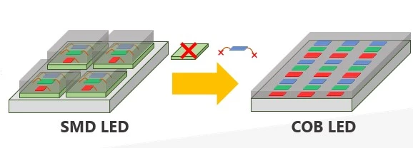
Figure 1: IMD Mini LED vs SMD

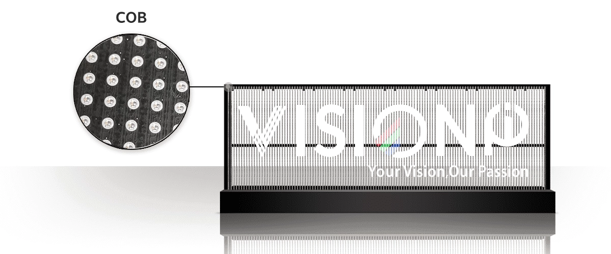
COB LED with no extra layer and bonding wires required copy

Figure 2: IMD mini LED vs COB

Advantages:

Higher reliability. Compared with traditional SMD, IMD has better anti-collision performance and higher SMT efficiency. Compared with COB.

Higher color consistency. IMD combines the advantages of traditional SMD and COB and has properly addressed issues in damage protection, black consistency, seamless splicing, light leakage

Lower maintenance costs, especially when there is only a single diode to be repaired. , and maintenance. It features a higher contrast ratio, higher integration, easier maintenance, and lower cost, which makes it an ideal product for the evolution of finer pitches.

Lower Manufacturing Cost. Traditional SMT 1010 machines can still be used for the production of IMD with a similar manufacturing process. By keeping the SMT process, LED display manufacturers can move to IMD display production faster, due to the existing mature SMT supply chain.

Disadvantages:

With the continuous narrowing of pixel pitch, IMD faces the same problem as SMD-there will always be a physical limit, leaving limited room for IMD product growth.

Without further subdivision of bins by chip suppliers, IMD’s bin-selection process becomes more difficult as it has multiple RGB chips per package. The uniformity and consistency of RGB chips in each package may not be as high as LED displays made of individual SMDs.

advantages and disadvantages of IMD

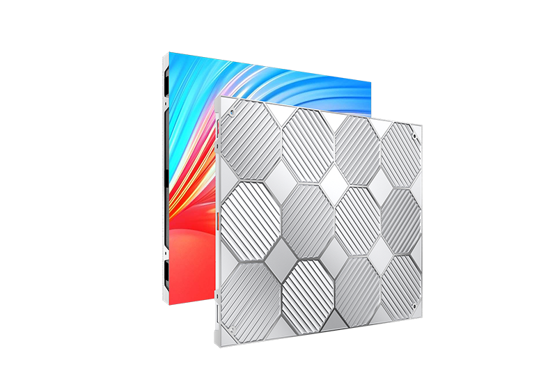
Mini LED Display: Fixed Installation

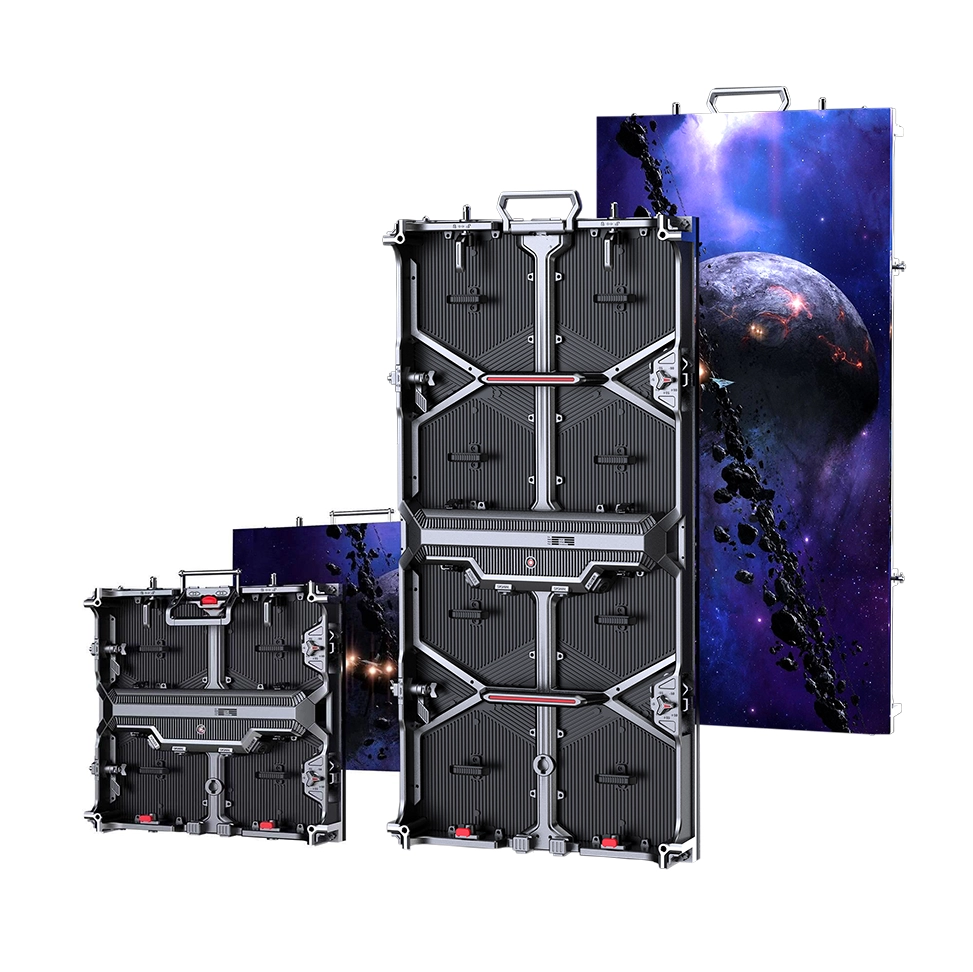
Dimension: 500*500*74.3mm

Pixel Pitch Indoor: Mini LED 1.95mm, 2.6mm

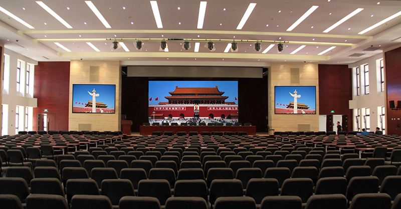
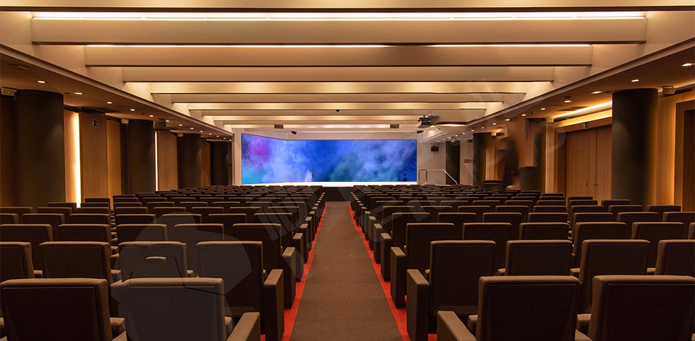
Applications: XR studios, TV stations, exhibitions,conferences, etc.

MINI LED RENTAL LED DISPLAY copy

4 in 1 Mini LED

imd rental led display p1.9

Mini LED Rental Display P1.9 2.6

Key Features:

● Unique Mini 4in1 LED,can bear 13kg impact force per pixel.

● High contrast ratio to 10000:1.

● Reduce more effect during camera shooting.

● High brightness up to 1500nits.

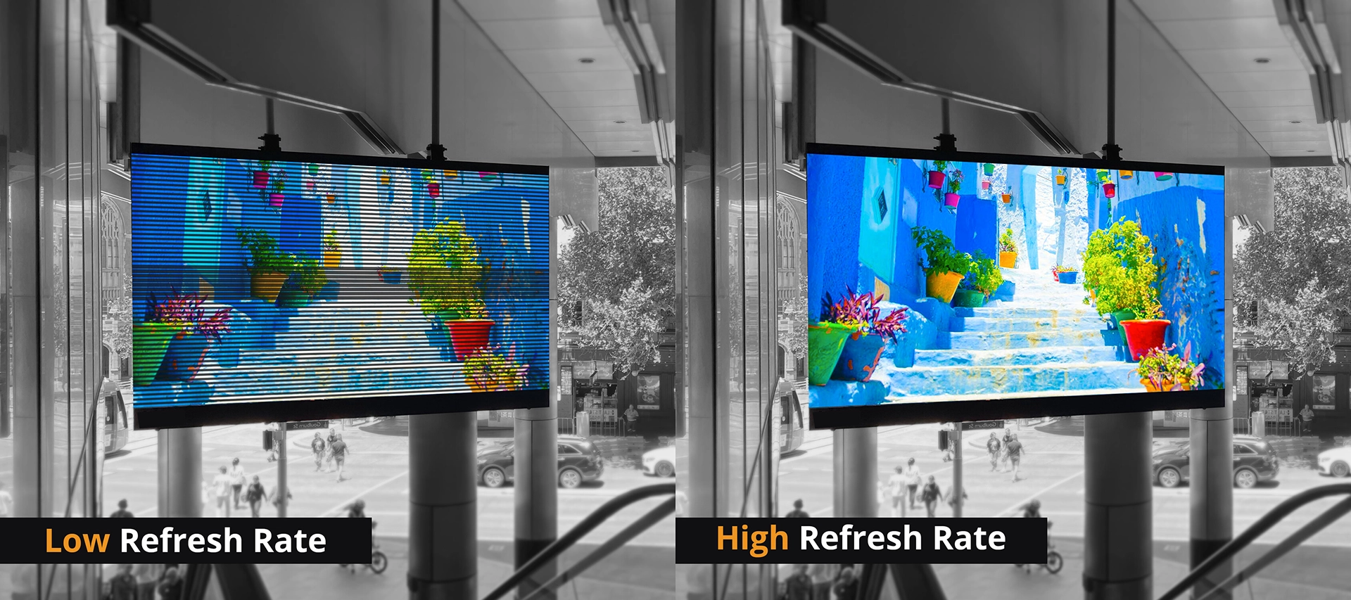
● High refreshment up to 7680Hz.

 Intelligent module.

Mini LED and Micro-LED

What is Mini LED and Micro LED led display?

The Micro-LED concept was first put forward in 2000. In 2017, Mini-LED, as a subordinate form of Micro-LED, was introduced as a groundbreaking product, officially opening a new chapter of Mini and Micro-LED.

Definitions of Mini/Micro-LED vary in the industry. On one hand, upstream suppliers and LCD display manufacturers tend to define Mini-LED and Micro-LED by chip size, formal or flip structure, and film transfer (substrate-less structure). On the other hand, large-format display manufacturers are more inclined to define Mini-LED and Micro-LED by pixel pitch and packaging method.

Definition of Mini LED and Micro LED

I1.In terms of pixel pitch. products at or below 2.5mm are defined as fine-pitch, which serves as an umbrella term. Within the fine-pitch range, Mini-LED is defined as products with pixel pitch ranging from 0.4mm to 1mm, whereas Micro-LED is defined as products with pixel pitch below 0.4mm.

2 In terms of packaging. fine-pitch displays (typically below 1mm) made of IMD and COB are considered Mini-LED displays. Micro LED is powered by COB technology and COG technology.

LED displays have been used in commercial applications for more than a decade. IMD extends the service life of the SMD supply chain and serves as a smooth transition from SMD to finer-pitch products. COB’s growth paves the way for Mini- and Micro-LED products in the future.

3.In terms of Chip Size. Mini LEDs tend to measure below 200 microns , while micro LEDs can be as small as 100 microns, or 0.004 inches.

Market competition brought by Mini & Micro-LED

With LED displays evolving to the fine-pitch level, viewing distance is also greatly reduced, which broadens the applications for fine-pitch LED displays. Indoor LED displays start at 4mm, and fine-pitch products start from 2.5mm. Further finer pitch in the sub-1 mm range will bring LED displays to the consumer market and ultimately compete against LCD and laser projections in the TV market.

108 Diagonal LED Display in Different Pixel Pitches

Take the 108-inch LED display as an example (600*337.5mm LED panels in 4×4 panel array). When the pixel pitch is P1.25, P0.62, and P0.31, the resolution can be 2K, 4K, and 8K respectively. According to the Rec. ITU-R BT.1769 reference standard of ITU (International Telecommunication Union), the optimal horizontal viewing angle under this resolution is 32°, 58°and 96°respectively, from which the optimal viewing distances are estimated to be 4.17m,2.02m and 1.01m respectively. The above viewing distance makes it possible for LED displays to be used in living rooms as a TV. The viewing distance of 2.02m and 1.01m is suitable for the living room area of most houses. From another perspective, if we convert the resolution of 2K and 4K LCD TVs into pixel pitches of 53” LED displays, we can find that 2K LCD TV’s pixel pitch is between 0.6mm and 1.2mm, and 4K LED TV’s pixel pitch is between 0.3mm and 0.5mm. Up to now, SONY, Samsung, and other display manufacturers have launched large-size Mini/Micro-LED display products up to 120 inches based on a modular design. If we ignore their sky-high price, these products are perfect for living room applications. 

2K and 4K LED Display in Common LCD Display Sizes
Comparison of LCD, DLP and LED

Common Cathode VS Common Anode LED

Common Anode LED Display

Common anode LED screen has all of the anodes of the individual LEDs connected together and to a common terminal, while the cathodes of each LED are connected separately.

Common Cathode LED Display

A common cathode LED screen is also called” energy-saving led display”. It has all of the cathodes of the individual LEDs connected together and to a common terminal, while the anodes of each LED are connected separately.

common cathode”. It is an energy-saving power supply technology for LED displays where the current first passes through the LED chips and then reaches the negative pole of the driving IC, hence the name “common cathode”. The voltage drop and current loss can be reduced by using the independent voltages power supply method. Additionally, this technology can separate and precisely power the red, green, and blue LED chips. LED professionals know that the rated power required for the red, green, and blue chips is different, and ordinary power supply methods cannot separate them and can only provide them with the same power. With an independent voltage power supply, the red, green, and blue LED chips can be separately and accurately powered, providing different voltages to them under the same current, which can ensure that they work at their rated power, thereby improving energy utilization and reducing energy consumption.

outdoor fine pixel 1.2 1.5 1.8 led display

Common Cathode Fine Pixel Outdoor LED Display

Common Anode and Common Cathode Structure Difference in Packaging

Common Cathode VS Common Anode LED display, which is better?

In the early stage, LED displays were mostly used for outdoor applications using larger pitch products, which did not have a physical space limit for driver ICs as they were designed with static scan drive. However, when LED displays began to be used for indoor applications using smaller pitch products, the space available for electronic components was squeezed, and as a result, dynamic scan drive (line-scanning drive) based on time-division multiplexing (TDM) came into being.

Under line-scanning drive mode, LED displays can be categorized into two types: the common cathode and the common anode.

As the name implies, common anode means individual LEDs are connected via their positive ends and driven by negative ends; and common cathode means individual LEDs are connected via their negative ends and driven by positive ends, and in common cathode mode, R, G, B chips are separately powered with voltage and current precisely distributed to red, green, and red diodes, and the current passes the diodes then to the negative ends of ICs.

Common Cathode VS Common Anode LED Schematic Diagram

common anode and common cathode led
common cathode led display voltage
When LED displays originally used separate R, G, B chips, LED drive technology was not a big concern for PCB design engineers. The following stage of LED displays, where RGB chips were encapsulated into one package, changed LED drive technology accordingly. In the fine-pitch era, the importance of common cathode technology increased, especially in sub-1 mm products.

The difference between the common cathode and common Anode

The direction of the current flow

■ In common anode mode, the current of LED displays flows from PCB to LED diodes, and the RGB LEDs are powered with the same power source at the same power rate, and therefore the forward voltage drop is increased.

■ In common cathode mode, the LED display’s current first passes through LED diodes with R, G, and B LEDs separately powered. Voltage and current are precisely distributed based on individual needs, then to the negative ends of ICs. The forward voltage drop is reduced, and as a result, there is less internal conduction resistance.

The supply voltage

■ In common anode mode, the LED display provides RGB LEDs with a unified voltage higher than 3.8V (such as 5V), therefore the power consumption is high.

■ In common cathode mode, the LED display provides RGB LEDs with separate voltage based on actual needs (2.8V for the red LED, and 3.8V for the green and blue LEDs). Because of this separate and precise power supply, the power efficiency is higher. Consequently, less heat is produced as less power is consumed.

 Energy efficiency and cooling effect

■ Based on accurate power control, common cathode technology can reduce the power consumption of the entire system by reducing the red LEDs’ supply voltage. Moreover, there are no extra line-scanning devices needed to achieve this. By using common cathode technology, LED displays can reduce excessive heat and power consumption, pixel failure rate, and ghost lines (tailing effect), thus improving LED displays’ overall performance

Supply chain

■ Common cathode technology reduces forward voltage drop by reducing the supply voltage of red LEDs, however, this requires the use of more power supplies, which further increases the complexity of the component layout on PCBs. Currently, the key supporting components related to common cathode technology are LED diodes, power supplies, and driver ICs. These components have market-proven solutions for common anode technology but are still in the early stages of common cathode technology.

How to calculate the power consumption of led display

Assuming that under common anode mode, a 5V voltage is used as the unified power, under common cathode mode a 2.8V is used for red LEDs, and all other conditions are the same if the current of red LEDs accounts for 40% of the total current, then we can quickly calculate the percentage of power saved: 40%*(5-2.8)/5=17.6%. If the ed LED current accounts for 50% of the total current, then we can save 50%*(5-2.8)/5=22%, Therefore, there is a theoretical 17.6%~22% power savings using common cathode technology over common anode technology.

Common Cathode LED Display saving cost.

•  1). Electricity, save operating costs: accurate power supply to reduce led display power loss, reduce operating costs.

•  2). No-cooling systems required: low heat temperature rise can also save the air conditioning, fans, and other cooling equipment.

•  3). Maintenance and repair costs: the subsequent fully enclosed die-casting aluminum chassis, the components are maintained one by one, making the led display life is about 2 times that of ordinary screens.

energy saving led display visionpi
energy-saving power consumption led display

Common Cathode Energy-saving LED Display

Common Cathode COB LED Screen

Ultra-low power consumption & temperature riseThe indoor common cathode LED screen can effectively save energy and dissipate heat through the flip-chip LED plus common cathode drive.

cob led screen P1.25
common cathode COB LED SCREEN

Common Cathode Outdoor Fine Pitch LED Display

The Common Cathode Outdoor Fine Pitch LED Display series, with pixel pitches of 1.2mm, 1.5mm, 1.8mm, and 2.5mm, provides unmatched clarity and durability for outdoor environments. Utilizing cutting-edge common cathode technology, these displays significantly reduce power consumption and heat output, all while maintaining high brightness levels. This ensures reliable, long-lasting performance, even in the most demanding outdoor conditions. Whether for advertising, events, or architectural installations, these displays offer vibrant, high-definition visuals with exceptional stability.

outdoor fine pixel 1.2 1.5 1.8 led display
fine pixel pitch outdoor specification

The future of led displays is to be more energy-efficient and environmentally friendly and to provide high-performance and low-power products that can solve the customers’ problems. The LED display should also be easy to maintain so that it can work stably for a long time. The LED display production technology is becoming more mature, and the future development of LED displays will focus on meeting the personalized needs of customers with energy-saving and easy-maintenance features.

Contact us today to learn more about how our LED displays can enhance your outdoor projects and deliver exceptional visual impact.

The Technical Definition of SMD

SMD is the abbreviation of Surface Mounted Devices, which results from the SMT (Surface Mount Technology) process. Based on different packaging structures, SMD LED products can be divided into two categories: TOP LED and CHIP LED.
SMD Display Manufacturing Process
Mainstream product specifications Currently SMD fine-pitch displays mainly use the following diode models:
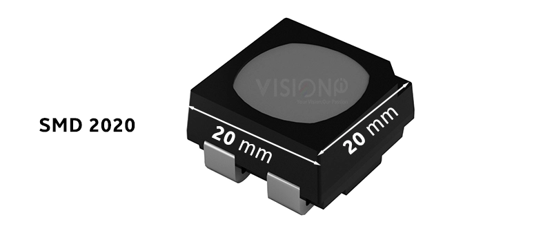
2121,1921,1820,151 5,1415,1212,1010, 0808 and 0606. The smaller the diodes, the finer pitch they can be used for. However, SMD 0808 and 0606 tend to be less reliable as individual LED diodes used for sub-1 mm products.
SMD Diodes Roadmap

 Advantages and disadvantages of SMD :

Introduced in 2001, SMD packaging technology is highly mature for 1mm and above products, whether for indoor or outdoor applications, with almost two decades of development. SMD has a well-established supply chain with complete equipment and experienced production lines for mass production. SMD diodes are highly reliable and easy to repair, and the cost is relatively low compared to other packaging methods. 

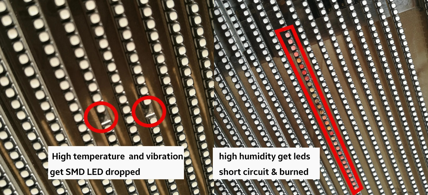
SMD surfaces are not sealed like COB’s, therefore the level of protection against water, dust, and external force (during transportation and installation) is not as high as expected. This is why fine-pitch LED display installation becomes a white-glove job, requiring delicacy and experience. Some SMD LED displays use a module mask (shader). In high-temperature environments, mask bulging is likely to occur, which will affect viewing. In most cases, the mask surface may turn white or yellow after a period of use, which may also degrade the user experience. Pixel pitch at or below P0.7mm presents physical limitations. Due to the size of SMD packaging and welding wiring layout space on PCB boards, it is challenging for SMD displays to advance to finer pitches.

Evolution and status quo of LED display packaging

LED display packaging has developed from early-days DIP (dual in-line package) to today’s multiple packaging methods such as SMD, IMD, and COB,. These methods have reshaped the industry.


Since the advent of SMD in 2001, the market share of DIP (direct insertion pattern) packaging has been shrinking annually. However, DIP is still used to ensure product reliability in harsh environments like high-altitude or ultra-low temperature conditions. SMD has played a dominant role in LED packaging for more than a decade. It was not until 2016 that COB began to attract more market attention.
In 2017, SONY launched a Micro-LED display based on flip-chip COB, which inspired the industry to further explore the COB development path. At the end of 2017, the concept of Mini-LED was raised. That greatly accelerated the evolution of pixel pitches towards a finer level. Limited by technology and equipment, conventional single diode SMD packaging reaches it’s smallest size at 0.5*0.5mm. Any smaller packaging size from this point is no longer processable by the current SMT process. This physical limit encouraged the entire industry to explore other technologies such as COB (especially flip-chip COB) to continue its technological evolution.
In 2018, NationStar launched its 4-in-1 IMD09 and put forward the concept of IMD, which combined the advantages of both SMD and COB. This officially began the three-way race between SMD, IMD, and COB in the fine-pitch LED display industry.
 Evolution of LED Diodes Packaging 2000-2019

Subscribe To Our Newsletter

Join our mailing list to receive the latest news and updates from our team.

You have Successfully Subscribed!

Pin It on Pinterest