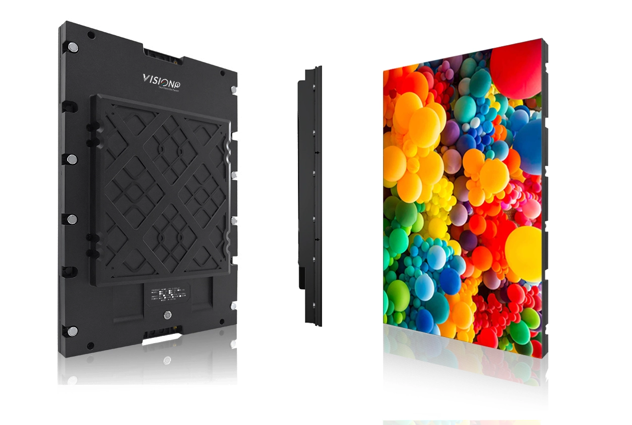
How to Install Indoor LED Wall
How to install indoor led wall
1. Preparations
1.1. Unpacking
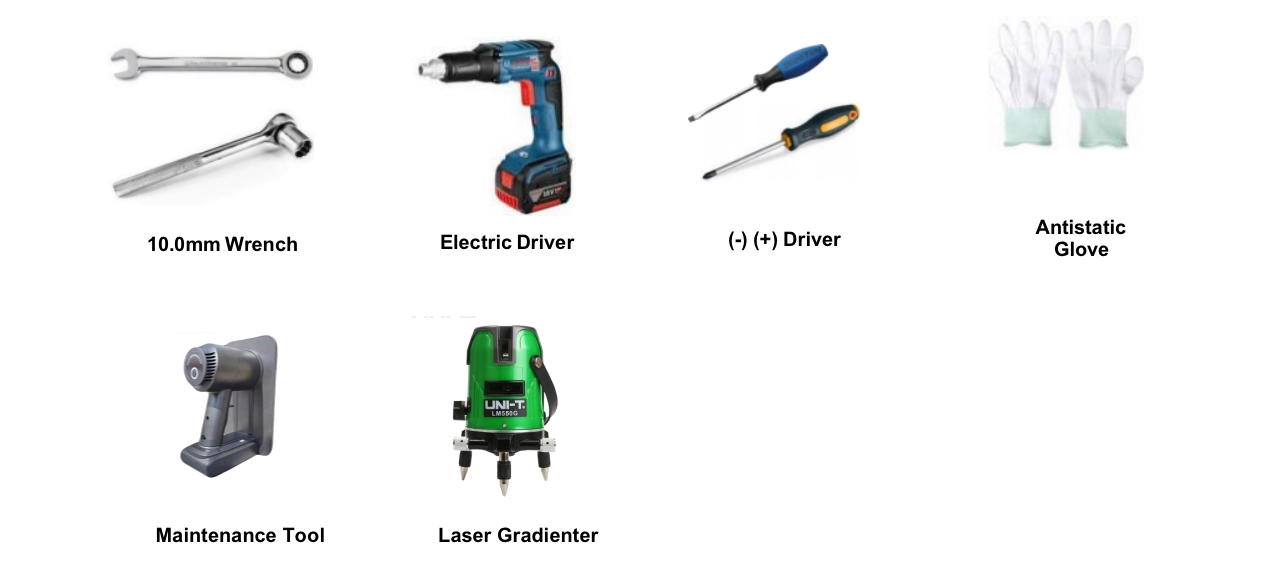
Warning: To prevent damage to the LED panel, wear anti-static gloves before installing/touching the display. After unpacking, do not place the display vertically on the floor, an accident such as a fall may be caused.
Die-casting LED Display Cabinets Installation
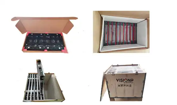
• Power cable;LAN cable (RJ45, CAT-5)
• Connection plates
• LED Controller
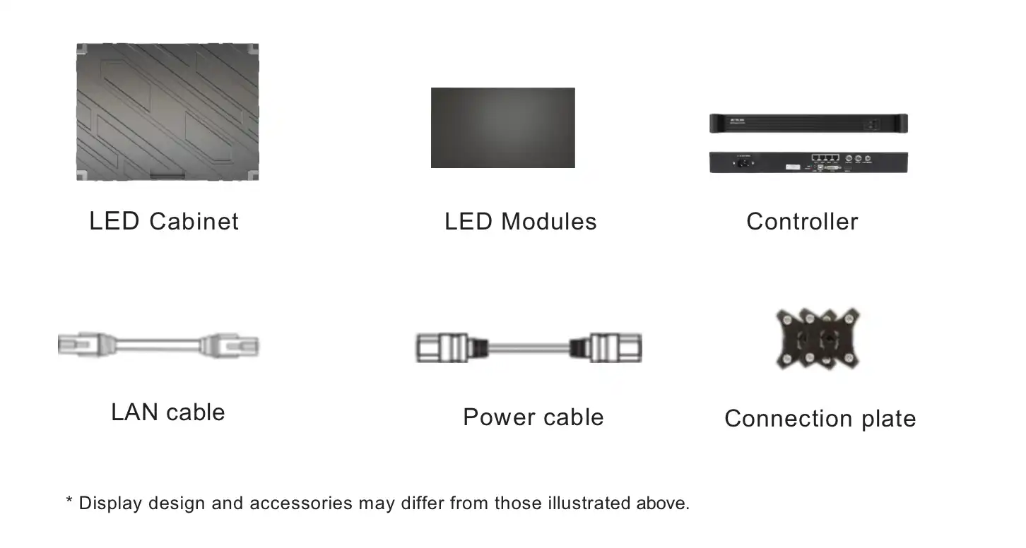
• LED Cabinets &LED Modules
• Power cable;LAN cable (RJ45, CAT-5)
• Connection plates
• LED Controller
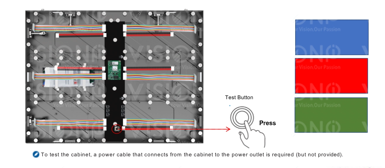
Press the CHECK button on the back of each cabinet to check if the product can operate normally.
2. Structure Installation
Precautions when handling the cabinets:
• Do not drop or apply shock/vibration to the product. Strong impacts may damage the component inside.
• Only a qualified service technician should perform the installation.
• Only use approved cabinets. • Be careful not to damage the corners of the cabinet.
• Install the display in a well-ventilated area.
• Always wear anti-static gloves when touching the display.
• Provide air conditioning around the LED display to allow heat dissipation away from the display.
• To maintain proper ventilation, keep clear space from the mounted displays to the wall. Installing the product in poorly ventilated spaces may damage the LED.
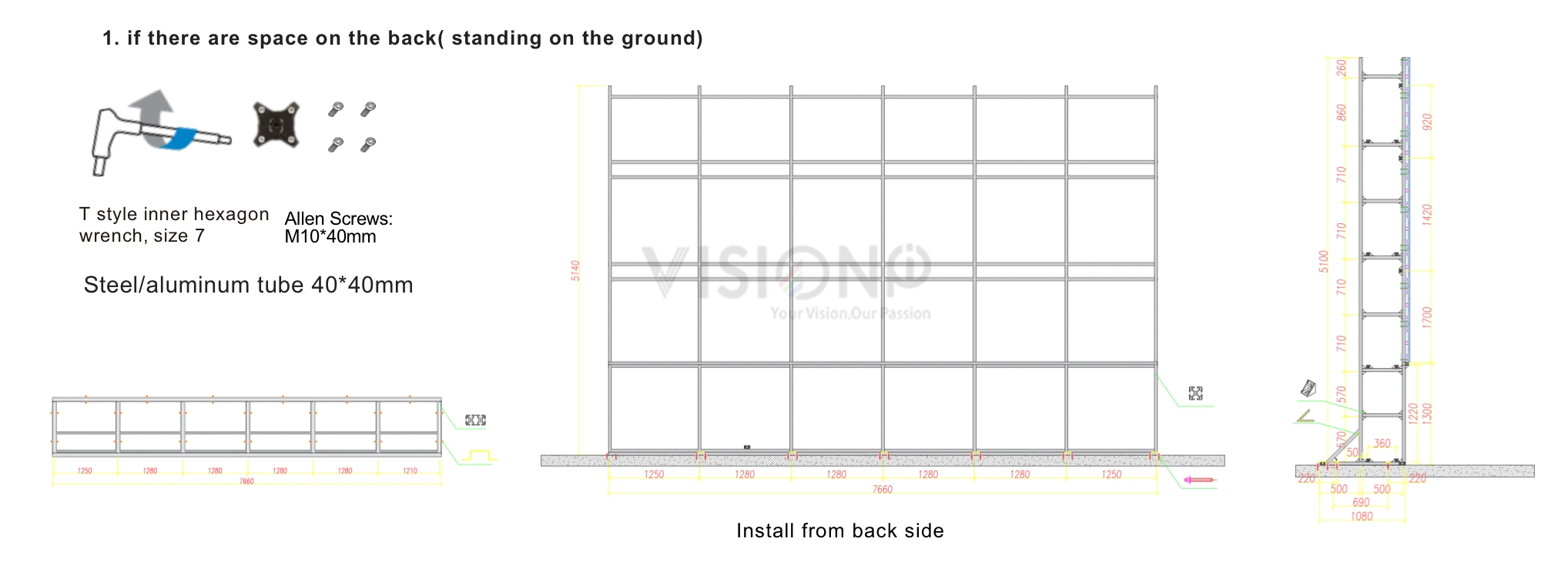
Wall Mount Kits
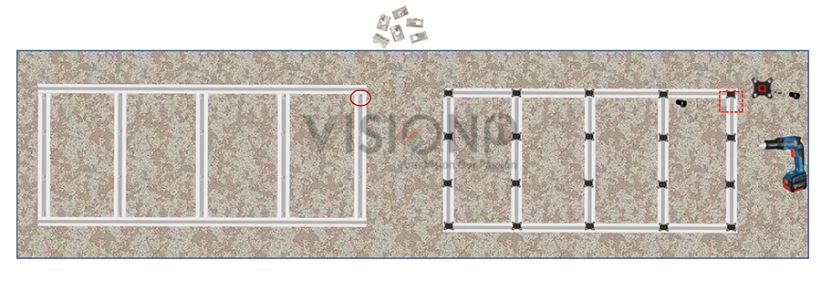
A wall mount kit is made of aluminum profile 40x40mm (in some regions sold separately or available from third party vendors) allows you to mount the LED display on the wall. For detailed information on installing the wall mount, see the instructions provided with the wall mount. Wall mounting can only be performed from the front side of cabinets.

2. Insert the connection plate on the structure, and use the Allen screw bolt to connect the cage nuts.
4. Install led modules (follow the arrow direction of the modules)
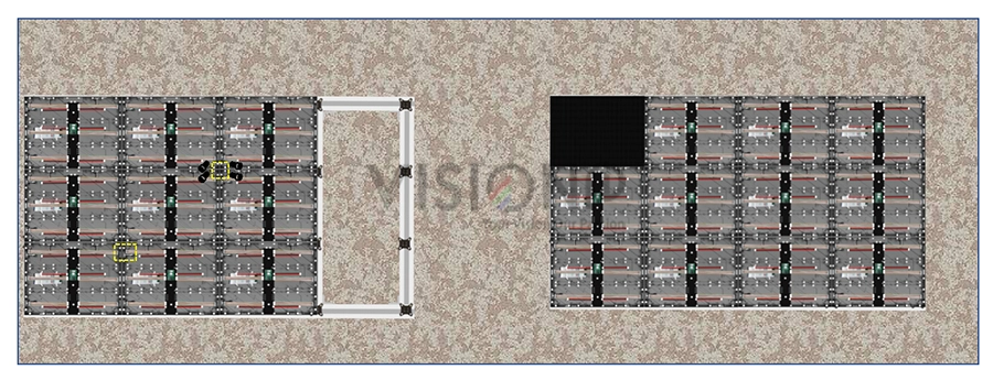
3. Cabinet installation
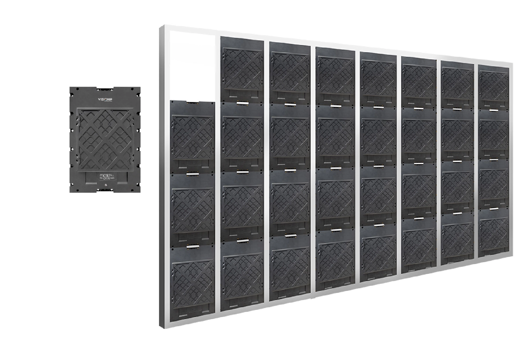
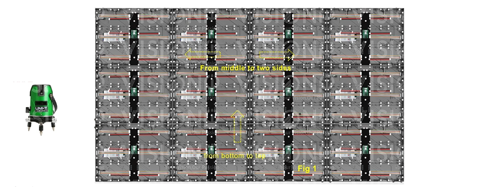
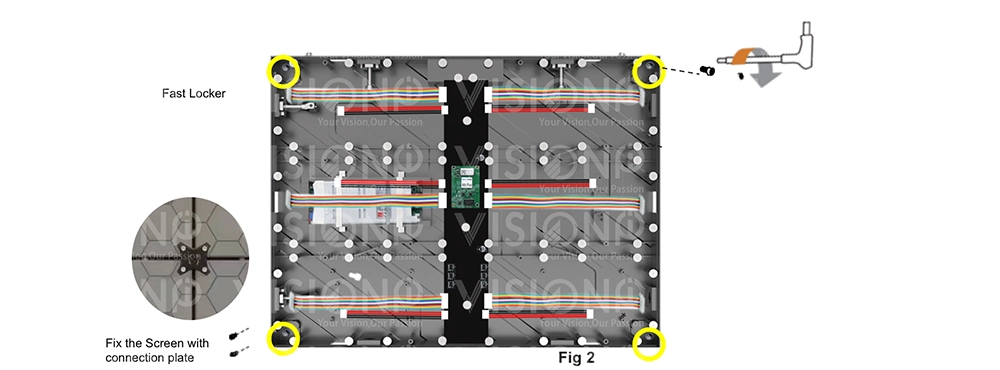
Step 1. Use a gradienter to adjust the flatness and verticality and then secure the cabinet to the connectors on the rack frames. Use connection plates to fix the screen. Start your installation from the bottom row. Install the connecting plates on the bracket (Fig 1). Rotate the hex key clockwise until the screw bolts are inserted, and fasten the fast locker on between two cabinets (left to right, up to down)(Fig2.) ※Do not fix the screws between the connectors and cabinets too tight for future adjustment.
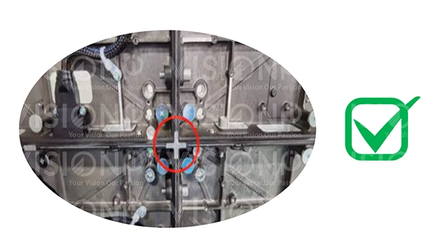
4. Power and Signal Wiring
The data wiring process must follow a zigzag order between the cabinets, always starting from the one located at the bottom left. The modules are then connected to the data in and data out ports. Thanks to our system software we can verify the correct wiring of the entire screen with simple tests. Finally follows the color calibration and brightness setting.
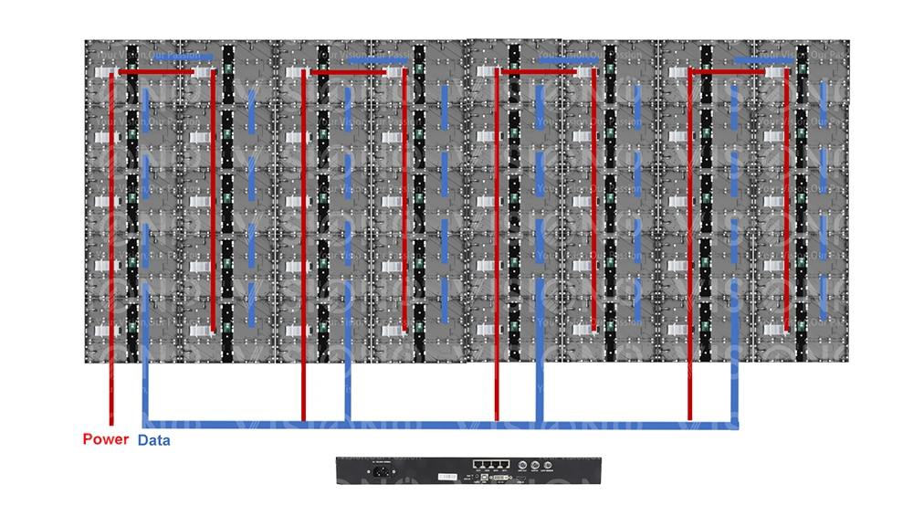
5. LED Modules installation.
After check all the cabinets are well installed, attach the led modules to the cabinet, please check the arrow on the back of the PCB and follow the direction, and connect the flat cable and power cable from the hub to each of the modules. tips: to check the status of each led module on the cabinet, you can use one spare cabinet to test the condition of the led modules by pressing the test button on the hub.
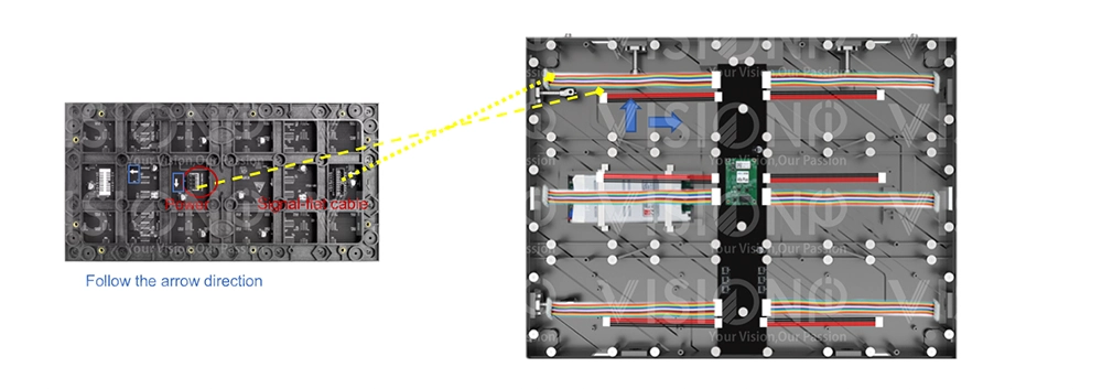
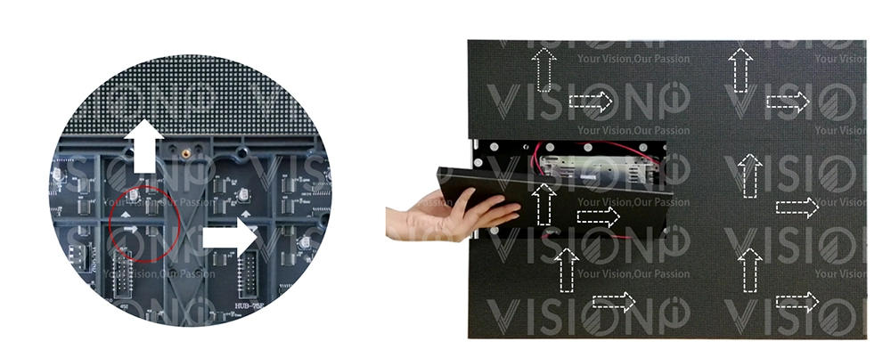
Modular Cabinet 320x480mm Installation
