Quantum Dot Micro LED Display
Micro LED Challenges
Micro-LED technology holds promise to outperform OLED and LED-LCD displays, but faces key challenges that need addressing:
- Red Efficiency
Red efficiency drops significantly when scaled to micrometer sizes due to carrier loss and nonradiative recombination at sidewall defects. This results in lower brightness and higher power consumption, hindering adoption. - Brightness and Color Gamut
While Micro-LEDs can theoretically achieve peak brightness up to 10,000 Nits and cover 100% of the Rec-2020 color gamut, current AlInGaP red LEDs struggle to reach 1000 Nits in real-world conditions, leading to high power consumption and reduced reliability.
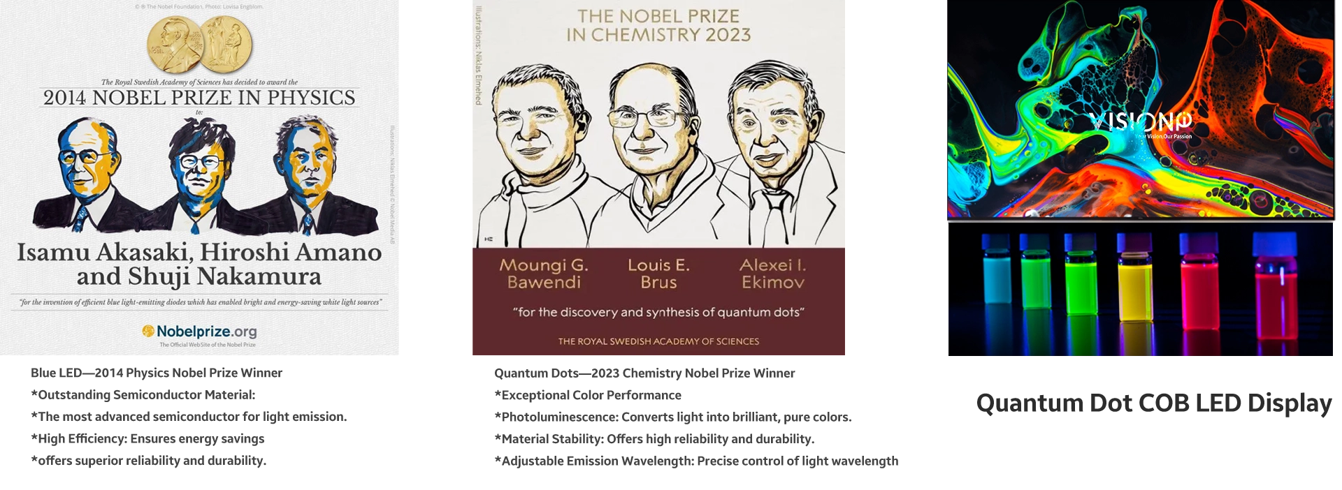
Quantum Dot LED Displays: Revolutionizing Micro-LED Technology
- High Efficiency: Achieves >99% color purity with ultra-thin QD layers.
- Enhanced Durability: 8x lower flux density ensures long-lasting performance.
- Superior Heat Dissipation: Nano-porous GaN enables >100W/m-K thermal conductivity.
- Cost-Effective: Converts affordable blue LEDs to RGB, reducing production costs.
- Precision Colors: ±0.5nm wavelength control for consistent, vibrant color output.
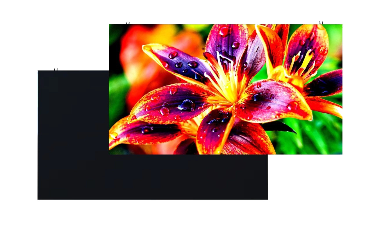
What Are Quantum Dots?
Quantum Dots are tiny, human-made particles with special light-emitting properties. They’re incredibly small, about 2 to 10 nanometers wide (that’s thousands of times smaller than a grain of sand). When light hits a Quantum Dot, it glows in a specific color. The color depends on its size: Big dots emit reddish light.Small dots emit greenish light.This ability to produce precise colors makes Quantum Dots ideal for vibrant and accurate displays.
Quantum Dot Micro LED Display
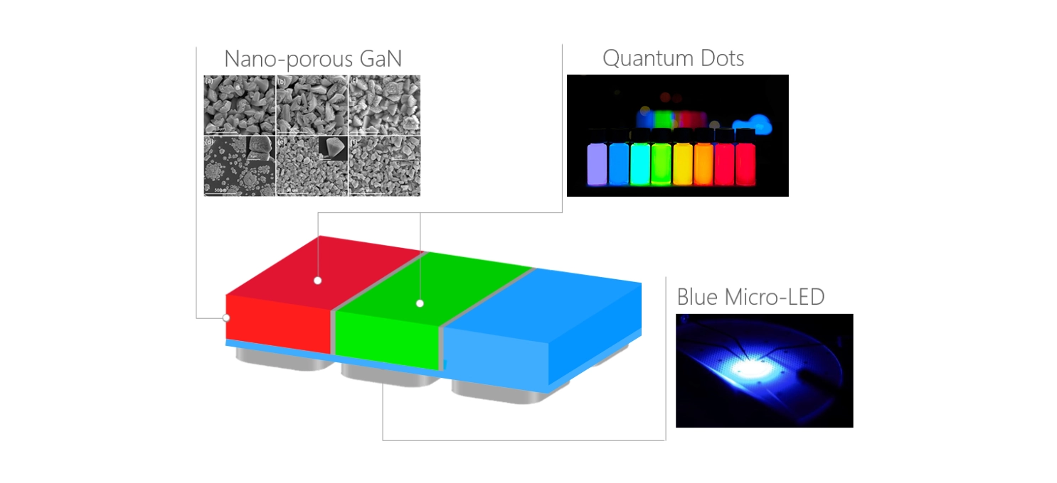
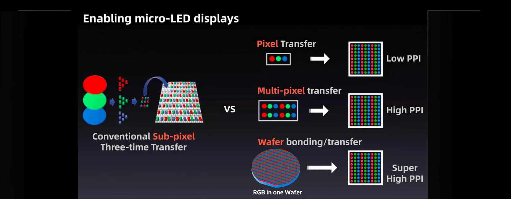
A Quantum Dot Micro-LED display uses electrochemical etching to create a nano-porous layer inside the GaN LED. This porous structure is then filled with quantum dots (QDs) that emit red (R) or green (G) light when excited by blue light. As a result, the display achieves addressable red, green, and blue (R-G-B) pixels within a single monolithic chip, providing enhanced color performance.

Traditional COB LED displays are comprised of red, green, and blue chips, each constructed from different materials. Green and blue chips typically use Gallium Nitride (GaN), while the red chip is made from Gallium Arsenide (GaAs). These material differences result in variations in light emission angles, temperature sensitivity, and production processes.
In contrast, Quantum Dot COB LED displays utilize blue light to excite quantum dots, which then emit red light. All three color chips—red, green, and blue—are fabricated from Gallium Nitride (GaN), ensuring consistent light emission angles across the entire color spectrum. Additionally, the brightness of these chips exhibits minimal sensitivity to temperature fluctuations, improving RGB color consistency even under varying temperature conditions, and ensuring stable, high-quality display performance.
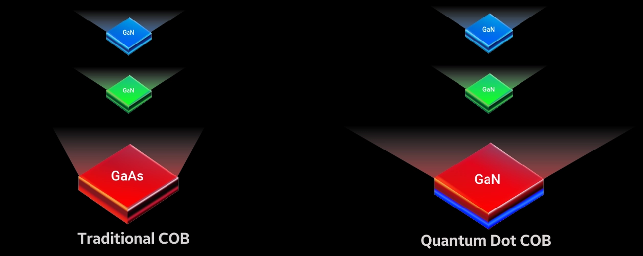
Quantum Dot COB LED D display VS Traditional COB LED Display
Quantum Dot COB LED Display Features
No Substrate Transfer—Improved Yield
Quantum Dot red and blue-green light chips share the same substrate, eliminating the need for substrate transfer. In contrast, traditional GaAs chips require conversion to sapphire substrates, a process that leads to significant yield loss and increased cost.
Superior Color Uniformity under wider Viewing Angle
Quantum dots LED screen offer precise control over their wavelength, allowing for exceptionally narrow wavelength distribution. This ensures that the wavelength variation within and between wafers is limited to just ±0.5nm, resulting in highly consistent and pure colors across the display.

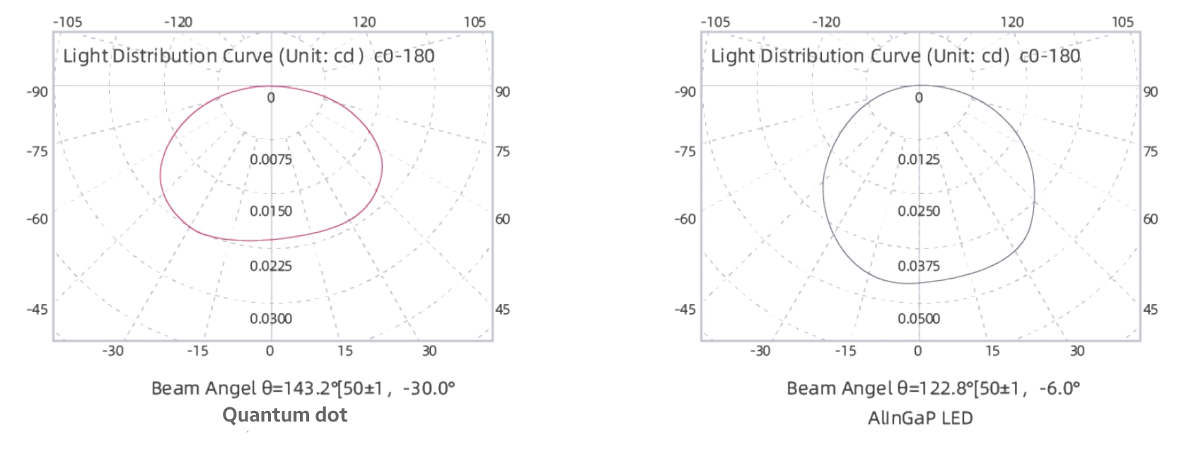
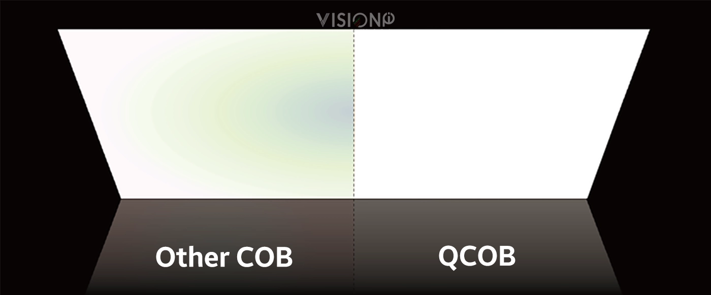
Wider viewing angle-No Color Deviation
Quantum Dot LED Screen offers consistent display performance across various viewing angles.By using uniform materials for all three colors, the light output is consistent, ensuring uniform display quality from any angle.
When the viewing angle shifts from 0° (front-facing) to 85°, the color deviation of Quantum Dot direct-view displays is reduced by 8 times compared to traditional displays, with color temperature differences being up to 12 times lower.
Superior Color Accuracy Across Temperature Variations
Due to the precise size control of quantum dots, Quantum Dot chips generate a narrow red light spectrum (2nm), ensuring exceptional consistency in red light output. Compared to traditional displays, Quantum Dot Micro-LED (QD-mLED) technology is significantly less sensitive to temperature fluctuations. As a result, color uniformity variations caused by temperature changes during startup are reduced by 20% compared to conventional screens, maintaining superior color accuracy across a wide range of temperatures.
Eco-Friendly Quantum Dot LED Screens
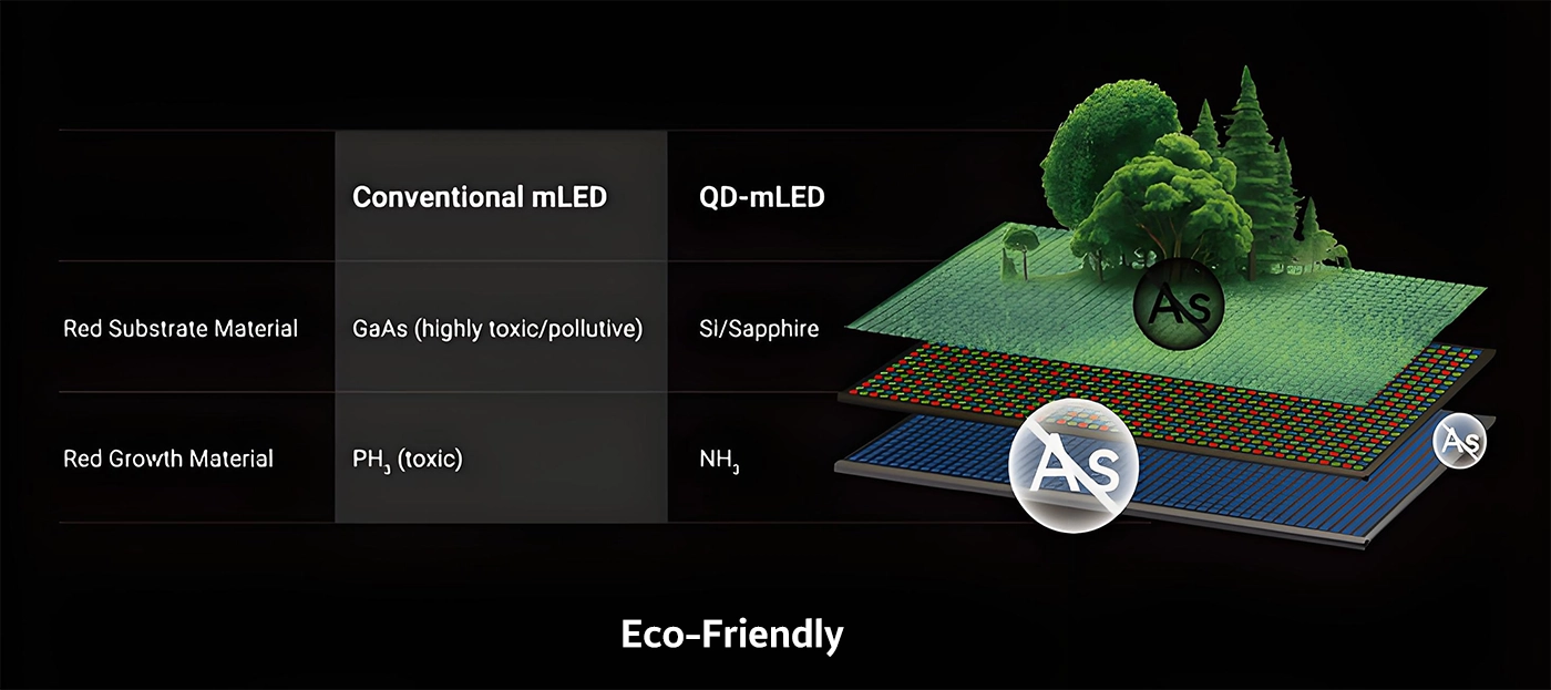
In traditional displays, the key materials for the red light substrate are Gallium Arsenide (GaAs) and Phosphine, both of which are toxic.
In contrast, Quantum Dot LED screens use eco-friendly materials: Silicon (Si) or Sapphire for the red light substrate and Ammonia gas (NH₃) for red light growth. This eliminates the use of harmful substances like Arsenic and Phosphine during the manufacturing process, making Quantum Dot LED screens a more environmentally sustainable option.
Reduced Power Supply Costs
In Quantum Dot Micro-LED (QD-LED) displays, the red light driving voltage aligns with that of the blue and green channels, eliminating the need for dual-voltage interfaces commonly required in traditional direct-view displays. This design optimization results in a 15% reduction in overall power supply costs.
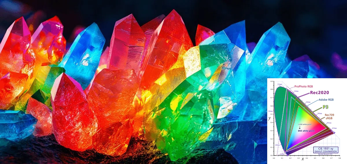
Enhanced Color REC 2020
Experiments have demonstrated that Quantum Dot COB LED displays deliver exceptional color gamut performance, achieving 80% coverage of the Rec. 2020 color space. This ensures vibrant and accurate color reproduction, enhancing the overall viewing experience.
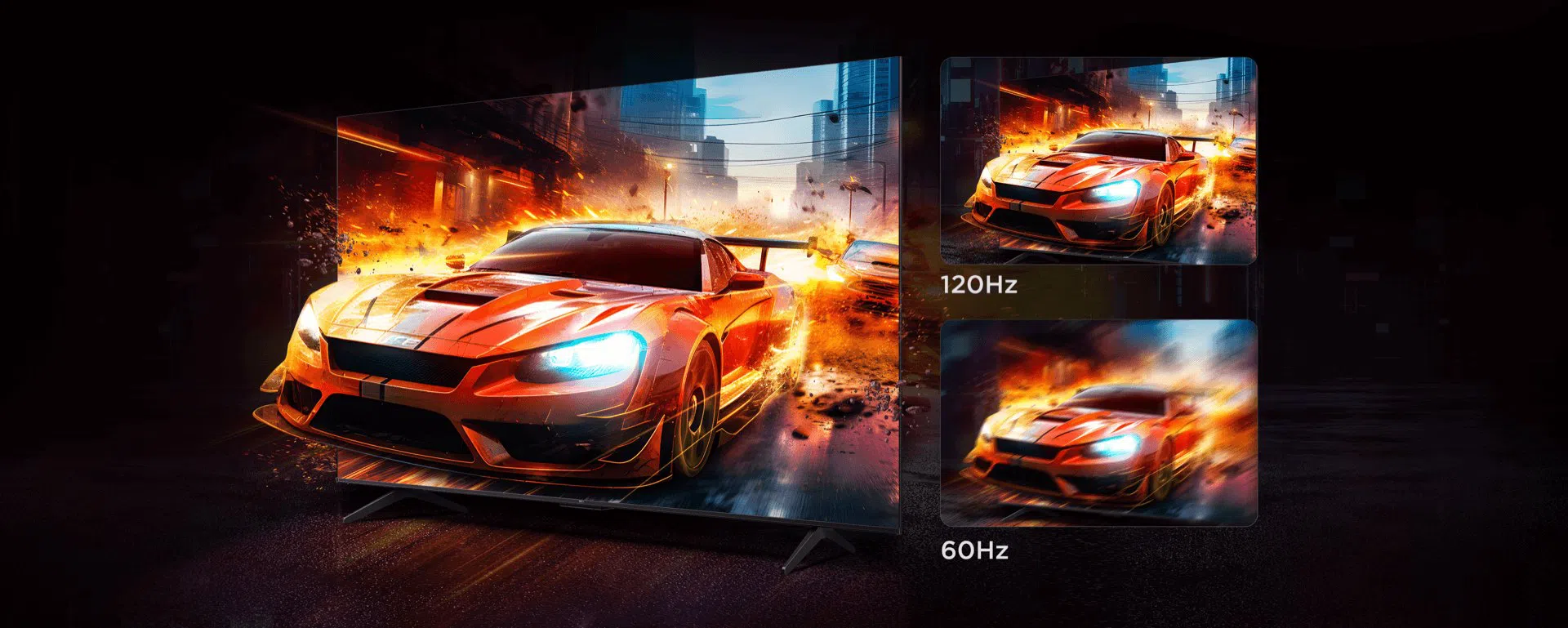
120Hz Broad-casting Level
With a 120Hz frame rate and broadcast-level performance, Quantum Dot LED displays are perfect for applications like cinemas, home theaters, and XR studios, delivering seamless motion and stunning visual quality.
Discover the future of display technology with Quantum Dot Micro-LED Display. Experience superior color accuracy, energy efficiency, and stunning brightness. Contact us today to learn more and elevate your display solutions!

