LED screen driving ic

Introduction of the led display driving IC

LED display driver IC is such a key component, it is like the central nervous system of the human brain, and it is in charge of the body’s physical actions and mental thinking of the brain. The performance of the driver IC determines the effect of the led display screen, especially the use of modern large-scale activities and high-end venues, making people more stringent requirements for LED display driver IC.

Driver IC’s role is to display data (video card or processor receives information from the source) in line with the agreement to receive in-house production time PWM.LED Driver IC chip can be divided into two: Classic and functional chip
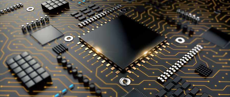
driving ic led display

IC Costs:

Classic Constant Current Chip is not designed specifically for LED, but some logic chips with an LED display portion of logic functions The chip is in accordance with special LED light emission characteristics designed specifically for the LED display driver chip. LED is a current characteristic of the device, that is, under the premise of saturated conduction, the brightness varies with the change of the current, rather than by adjusting the voltage across it varies. Therefore, one of the largest dedicated chip features is to provide a constant current source.

The constant current source can guarantee the stability of the LED drive, eliminating flicker LED, LED display is a high-quality picture premise. Functional chip: Some dedicated chips for the requirements of different industries also added some special features, such as LED error detection, and current gain control current correction.

Driver IC’s performance:

LED display performance indicators, an image refresh rate, and gradation expression are the most important indicators. This requires that LED display driver IC inter-channel current have high consistency, high-speed communication interface rate, and constant speed of response. In the past, refresh rate, and gray-scale utilization of three is a shift in the relationship, to ensure that one or two of the indicators which can be more excellent, would have been appropriate to sacrifice the remaining two indicators. For this reason, many LED display is difficult to practice both ways, either refresh is not enough, the high-speed camera equipment shoots prone black lines, or is not enough gray, and color brightness and darkness are inconsistent. With advances in technology driving IC manufacturers, now a breakthrough in the problem of three highs has been able to solve these problems. In the application of LED full-color display, in order to ensure user comfort for a long time with the eyes, low-light high ash becomes a test driver IC performance a particularly important standard.

The drive IC trends

1) Energy Saving.

As a green energy-saving LED display is an eternal pursuit, it is also considered an important criterion driver of IC performance. Saving driving IC includes two aspects, one is to reduce the knee voltage constant current, and thus the traditional 5V to 3.8V power supply to reduce the following; the second is through the optimization algorithm and IC driver IC design reduces the operating voltage and operating current. There are already manufacturers launching a 0.2V low voltage transition, improvements of up to 15% utilization of LED constant current driver IC, using 16 percent conversational products to reduce heat supply voltage, which greatly enhances the energy efficiency of the LED display.

2) Integrated.

With the rapid decline of the pixel pitch LED display on the unit area to mount packaged devices to grow exponentially, greatly increasing component density module drive surface. In a small pitch P1.9 LED, for example, 15 sweep 160 * 180 90 module requires constant current driver IC, 45 tube rows, 2 138. So many devices available to make PCB routing space become extremely congested, increasing the difficulty of circuit design. At the same time, so crowded arrangement of components can easily result in poor welding and other issues but also reduces the reliability of the module. Driver IC less the amount, the greater the PCB layout area, and demand from the application side of the driver IC must be Forced onto the highly integrated technology road map. And Rui Ling photoelectric RS1.9 small pitch LED display, is the case of so many devices make improvements, to ensure the reliability and stability RS1.9 the same circumstances, the use of highly integrated 48-channel constant current LED driver IC, the large-scale integrated circuit peripheral to the driver IC crystal cell, reducing the complexity of the application side of PCB board design, the constant current driver IC 180 reduced by nearly three times, constant current driver IC becomes 48. 45 sweep 152 * 171mm module requires only 48 constant current driver IC, 30 column pipe, line pipe 16, and two 245 signals. After developing and testing, we found even better results than the previous 180 constant current driver IC effect, but also play a role in energy conservation.

LED Display Driving IC brands

IC: MBI, Chipone, Silan, Toshiba, TI, SM Micro ( MBI and Chipone are very common in the market) Power supply: Delta; Greatwall, Meanwell, G-Energy, Chuanglian, Rong Electric, etc. ) Delta and Great wall are the best, Meanwell is well known in led display applications; G-energy is widely used by many factories, and Chuanglian Rong is at the same level.

MICROBLOCK: As the leading supplier of LED display driver ICs, our products have been chosen and applied to various world-class events, landmarks, as well as venues with specific demands and strict requirements such as control rooms. there are some recommended options for Different Applications:

CHIPONE was founded in 2008, Beijing. and grew up to be one of the leading led display drive IC companies in the industry,3 million pieces of LED display driver lit a large screen of the Tiananmen parade. The development of the Company is based on three aspects: cost-driven, technology-driven, and diversified product portfolio driven. Cost-driven means reducing the cost and improving product stability through the scale effect. CHIPONE has been a good alternative for MBI.more and more led display manufacturers are introducing chip one in their products. Chipone is one of the favorite brands, in recent years, especially for those led module manufacturers, here are some of the classic ICs: Basic: ICN2037.ICN2038.ICN2038S:1920HZ

LED Display Circuit Board

LED Display Printed Circuit Board (PCB) 

LED Circuit Boards(PCB)– the basement of the building. “LED Boards”, “LED blocks”, “LED panels”, “LED modules”, “LED cabinets” or simply “LED displays,” along with numerous other designations in the culture-specific parlance of the individual manufacturer, are in effect the biggest differentiated when comparing one SMD LED solution to another.

Pcb Board Mainboard Smd Processor Stock Footage Video (100% Royalty-free)  1014575498 | Shutterstock

Choosing a Good Quality PCB

Choosing the right circuit board material for LED displays is crucial for ensuring their quality and reliability. Here’s a simplified breakdown of what to consider and some popular options to help you make an informed decision:

1. Heat Conductivity

LED displays generate a lot of heat. Selecting materials with good heat conductivity helps manage this heat, keeping the electronic components at a stable operating temperature and preventing overheating damage.

2. Electrical Performance

The electrical performance of the circuit board material affects the flow of current and voltage. Key parameters to look out for include electrical resistivity, dielectric constant, and dielectric loss. These factors ensure smooth current flow and stable signal transmission.

3. Mechanical Strength

LED displays need to withstand mechanical stresses such as vibrations, impacts, and bending. Materials with high mechanical strength ensure the display’s structural stability and reliability.

4. Environmental Friendliness

With growing environmental awareness, choosing eco-friendly materials is becoming important. Avoiding harmful substances like lead and halogen compounds is crucial for both environmental and health safety. Look for materials compliant with environmental standards like RoHS.

Why Multiple Layers for LED Display

PCB, or Printed Circuit Board, layers are essentially the various levels or strata through which electrical connections are made in a circuit board. Think of a PCB like a multi-story building, where each floor represents a different layer with its own specific function, and stairs or elevators (vias in PCB terms) connect them together.

These layers house power circuitry and electrical grounding. Also, electronic circuitry to deliver, drive, and distribute both data for rendering the digital content and electricity to power the LED (Light Emitting Diode) will be housed in these layers. With respect to the “pixels” – the individual RGB LED packages – there are circuitry, diodes, resins, design elements, and peripheral surfacing materials/colors to consider as well.

  • Layer 1 (Top Layer): This contains the components like resistors, capacitors, and integrated circuits. It’s connected by copper traces that form the circuit.
  • Layer 2 (Inner Layer 1): Dedicated to ground connections. This layer helps in reducing electronic noise and interference, providing a stable environment for the circuit to function.
  • Layer 3 (Inner Layer 2): Used for power distribution. This layer distributes power from the power supply to various components across the board.
  • Layer 4 (Bottom Layer): It may contain additional components or traces that couldn’t fit on the top layer, or it could be used to complete circuits that start and end on the top layer.

How Many Layers of PCB for LED Display

For LED display PCBs, the number of layers required can vary significantly depending on the complexity, power requirements, and size of the display. Generally, LED displays can be categorized into simpler designs, such as those used in small consumer electronics, and more complex arrangements, like those seen in large outdoor or high-resolution displays. Here’s a general guideline:


What are the layers of a PCB (printed circuit board)? - Quora

Big Pixel pitch LED Displays

1 to 2 Layers :Simple (big pixel pitch) LED displays, such as those used in outdoor advertising P10,P8 or the single color led banners often use 1 or 2-layer PCBs. These are sufficient for routing power and signals to a modest number of LEDs without complex circuitry.

Moderate Complexity LED Displays

2 to 4 Layers: As the complexity increases(high brightness,high refresh rate)  with more LEDs and driving IC or the need for better power distribution and signal integrity, PCBs may expand to 2 to 4 layers. This allows for more sophisticated routing that can accommodate moderate densities of LEDs, improved heat management, and reduced electromagnetic interference (EMI).

High-Complexity LED Displays

4 Layers and Above: Large-scale or high-resolution indoor and outdoor LED displays, such as those used in outdoor advertising, stadiums, or professional-grade indoor displays, require 4 layers or more. These displays need extensive routing for hundreds to thousands of LEDs, necessitate excellent thermal management, and must minimize EMI. High-layer-count PCBs offer the necessary space for intricate routing and dedicated layers for power and ground planes, which enhances the overall performance and reliability of the display.

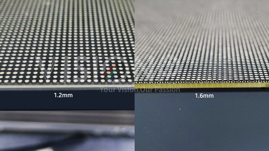
Material requirements: PCB board thickness:

The base material of most PCBs is a copper clad laminate consisting of fiberglass reinforced epoxy resin. Standard thicknesses for common laminate grades are:

  • 0.8 mm
  • 1.0 mm
  • 1.2 mm
  • 1.6 mm

Thinner laminates are more prone to warpage while thicker stacks can resist flexing and twisting forces.

generally 1.6mm thickness; Material: FR-4 glass fiberboard, some manufacturers may use FR-2 paper substrate in order to reduce costs.

led display modules pcb thickness webp

Copper foil thickness:

The thickness of the copper foil is the key to heat dissipation of the PCB board and the stability of the circuit. The normal copper foil thickness is 35um (1Oz), while one manufacturer will use the 18um (0.5Oz) copper foil. How can tell which standard they are making ? by weighting an empty, you can find out which is better, Under normal circumstances, the heavier the better.

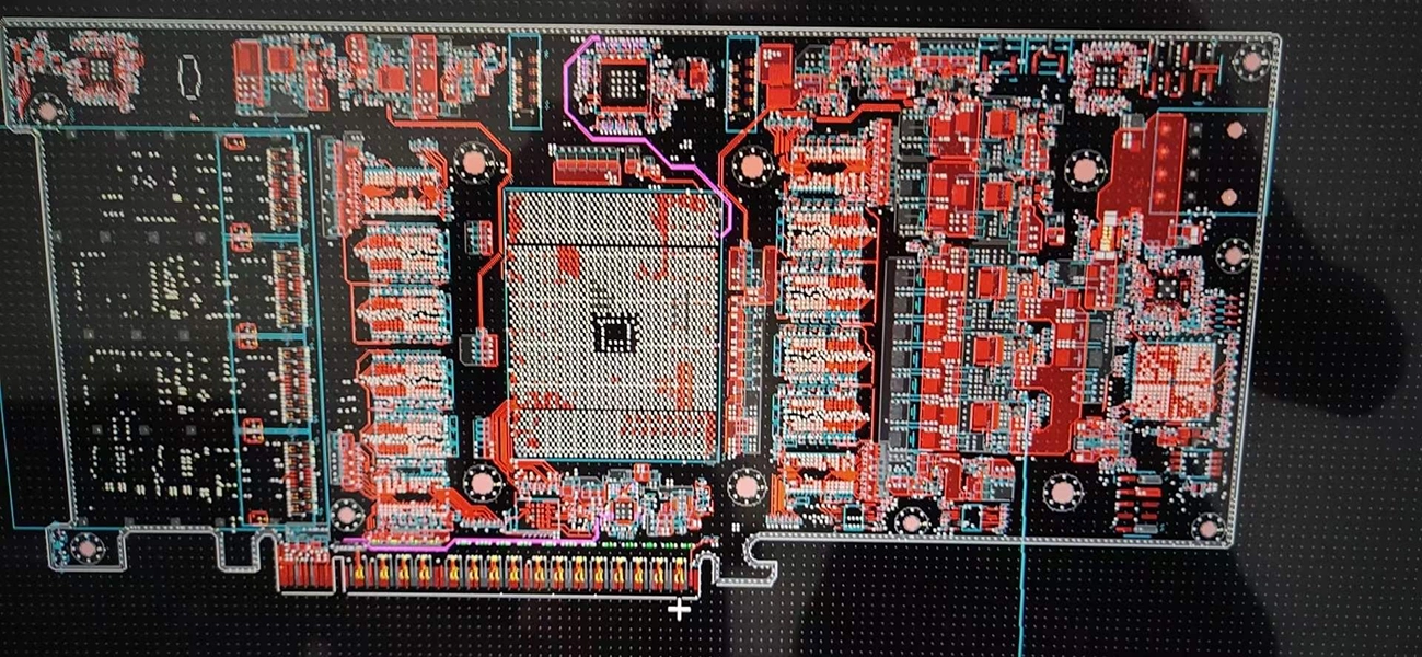
Circuit Design:

The designs of the actual circuitry to deliver data and power to the diodes are as different and recognizable in the LED display manufacturing industry as the brush strokes of Monet and Lautrec are in French Impressionism. This is where the real intellectual property of the individual manufacturers of these displays begins to differentiate the products.

The end game of these designs is to maximize the conversion of electrical wattage to light vis-à-vis heat. More light, less heat wins the race. Industry standards show that current typical circuitry design renders somewhere in the 60%-75% range as the percentage of wattage converted to light in the displays. This means the remaining 40%-25% of wattage is converted to heat. Depending on the environment where the display solution will be used that could be a problem. Imagine LED displays emitting a high level of heat in a high-end retail cosmetics store adjacent to say a lipstick PoP structure. A manufacturer who’s the elegance of design with their circuitry is rendering conversion percentages approaching 85% to-light efficiency.PoP structure. There is a handful of tier 1 (read: high-quality) display manufacturers who are the elegance of design with their circuitry, is rendering conversion percentages approaching 85% to-light efficiency.

How to check the PCB Design?

The distance between the “road” should be at least triple of the thickness of the “road”, the easiest way is to send to visionpi to check. we provide service to check the design. if you are interested to know more check our another article” what makes a good PCB layout design.

Industry standards show that current typical circuitry design renders somewhere in the 60%-75% range as the percentage of wattage converted to light in the displays. This means the remaining 40%-25% of wattage is converted to heat. Depending on the environment where the display solution will be used that could be a problem. Imagine LED displays emitting a high level of heat in a high-end retail cosmetics store adjacent to say a lipstick

led display pcb circuit design

LED Display Wavelength Selection

LED Binning of LED Display

LED binning is a complex process that ensures consistent performance and quality across LED Displays. It is employed to address the variations that occur during the industrial production of LEDs, even within the same product batch.

 Why LED Binning/ Batch match is important .

Improper binning can have several consequences when it comes to LED displays..If a display manufacturer were to indiscriminately purchase a run of packaged diodes from a diode manufacturer without any thought to the variation of optical and electrical specifications between the diodes, the display product they eventually manufactured would exhibit inconsistent performance.

Every display will exhibit small inconsistencies over time, but negligent binning will exacerbate the issues stemming from these inconsistencies, necessitating repeated calibration.

The process involves grouping LEDs with similar performance together in “bins” based on factors such as lumens, color temperature, voltage, and color.


Why the LEDs are different?

The diode manufacturing process is similar to the display manufacturing process in that each diode made in a production run will exhibit tiny differences from the others on its silicon wafer, even though they were all created with the same materials, ostensibly under the same conditions. Variations between diodes on separate wafers will be even more prevalent. The diode manufacturer will then pick and place the diode from these wafers into their packaging, complete the wire bonding (or wireless bonding), seal the package, and then sell these completed LEDs to display manufacturers. This can lead to inconsistent performance of the display product if the display manufacturer were to indiscriminately purchase a run of packaged diodes from a diode manufacturer without any thought to the variation of optical and electrical specifications between the diodes .

LED display Calibration

. Calibration is a smoothing process performed by display manufacturers before completing a display product. It involves gathering data on every pixel within a display using sophisticated optical equipment and running that data through analyzing software to generate a set of coefficients. These coefficients are then applied to each diode in the display to attune their performance down to the levels of the worst-performing diode

While calibration improves the consistency of the display, it reduces brightness. When not done correctly, it can result in a proportional decline in grayscale quality. As grayscale quality erodes, the slight differences between shades of the same color begin to fade. For example, on a calibrated display, Coca-Cola red may no longer be distinct from other reds. This can be problematic for brands that have paid good money to showcase their specific color

Ultimately, calibration is beneficial as it smooths overall consistency. However, a display should not require frequent calibration as it diminishes brightness and grayscale quality over time, lessening the impact of the displa

It is more complex and to understand the process it is necessary to introduce chromaticity diagrams.

The technique manufacturers use to make sure that the LEDs are similar is called LED binning.

It depends on that the LEDs are placed into similar categories – bins. With the bin defined is the similarity in:

  • lumens (Kelvin)
  • voltage (forward voltage)
  • color (wavelength)

Lumens and color are the most important parameters in LED variability.  Forward voltage is largely ignored in the binning process since it can be controlled and adjusted on its own by a display’s driver chip. Binning according to lumens is relatively simple to define – different than Binning LEDs according to color.  Each of these measurements comes with an acceptable tolerance ratio.

Tops you may be interested

Industry news

Supply Chain 

led Technology

Company News

LED Tips

White Paper

Quality Assurance

Manuels

LED Display Fill Ratio

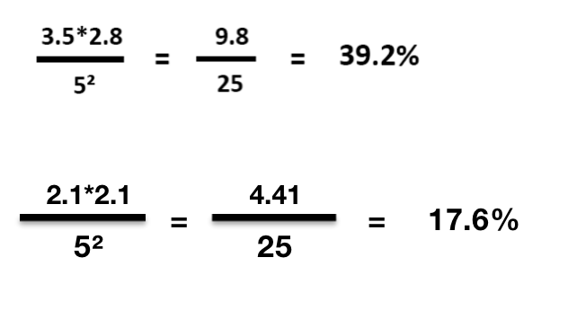
Fill Ratio-active VS inactive area As we briefly mentioned above, reflector cavities for LED packages come in several shapes, comprising greater or lesser percentages of active (light-emitting/reflecting) surface area of the package. The three most common shapes for these cavities are circular, rounded squares (similar to the shape of a radiant-cut diamond), and square. Since most of the industry uses an LED package referred to as a 35/28 SMD (which has a rectangular dimension of 3.5mm by 2.8mm) you can imagine which reflector cavity shapes allow for the highest active light regions within the package – square being the least and circular the most. The higher the fill ratio, the more lighted surface area. There is another component affecting this ratio as well. But some manufacturers will use 2121 for P5, which means the fill ratio will be only 17%, by using 2121 LED, They will save a lot of costs comparing with 3528 LED. Check the article “general SMD type for different pixel pitch led screens” to learn more about this topic. So which type of LED is reasonable to be used in different pixel pitches?

fill ratio

OUTDOOR:

>8mm ;10mm; 16 mm ——-3535 SMD

4.81 mm ;5mm ; 6mm ——2727 SMD

4.81 mm;5.95mm ————2525 SMD

2.6 mm–3.91 mm ————-1820 SMD

3mm;3.91 mm; 4mm ——– 1921 SMD

2.5mm-3mm———————1415 SMD

INDOOR:

2.5 mm -4 mm : 2020 /2121

SMD 1.875 mm-2.6mm :1515 SMD/1415 SMD

1.0-1.7mm : 1010 SMD

0.9mm– 0808 SMD

A lower fill rate can make the pixel pitch seem smaller without actually changing it, lighting area is smaller , it facilitates a better contrast ratio because there’s more black(black louver) visible against which the pixels can stand out. A higher fill rate on the other hand can make the pitch seem wider,The higher the fill ratio, the more lighted surface area ,while smaller black background. all else equal, and the larger a pixel is the more expensive it will be,the more brightness it will be.

Tops you may be interested

Industry news

Supply Chain 

led Technology

Company News

LED Tips

White Paper

Quality Assurance

Manuels

CHOOSING THE RIGHT LED DISPLAY!

CHOOSING THE RIGHT LED DISPLAY!

Video walls can create stunning centerpieces for a variety of spaces. LED video displays can transform any environment, but you may become overwhelmed when you look at all the options on the market. There are many elements to consider when selecting video screens, including indoor vs outdoor, pixel pitch, front vs rear serviceability, and shape. If you aren’t sure where to start, VISIONPI has products to fit every need.

So Many Video Wall Options—Where to Start

To get started, it’s essential to understand the basics. Here are some fast facts you should know:

  • An LED (light emitting diode) is a semiconductor device that emits visible light when an electric current passes through it.
  • LEDs require much less power than other types of screens powered by incandescent lamps, offering greater efficiency and a longer lifespan.
  • Indoor LED screens have wide-viewing angles, no color shifts, and have a smooth appearance from a short distance.
  • Outdoor LEDs are weather-proof, very bright, and are ideal for longer viewing distances.
  • Brightness is a key element in designing your video wall and is measured by nits. Indoor LEDs typically have 1000-1500 nits while outdoor LEDs have 2000-3000 nits. A nit is almost 3.5 times brighter than a LUX, the measurement of brightness used by projector screens.
  • Pixel pitch is another important part of LED selection. Pixel pitch is the physical distance from the center of one pixel to the next, measured in millimeters. The higher the number, the fewer pixels, and lower resolution. Depending on viewing distance, you’ll need to determine the right pixel pitch for optimal resolution. A general rule is 3.28 feet per 1mm of resolution.
  • Cost and budget are always a consideration. LEDs have a higher initial investment than projectors but last much longer.

Finding the Right Video Wall Equipment for Your Project

If you aren’t an AV expert, selecting the right LED video wall may seem difficult. It’s important to educate yourself on the basics of LED screens, as provided above. This gives you a foundation to begin your search. As you work with those that have specific expertise, like VISIONPI, you’ll know the right questions to ask about pixel pitch, brightness, and longevity.

To narrow down your selection, ask these questions:

  • How will you use the display? Does it need to be the central element in a setting? Or is it a backdrop?
  • Are you using the displays inside or outside?
  • Will it be viewed from long or short distances?
  • How will it be mounted? Does the area require a certain shape or curvature of the screen?

Depending on your answers, you can narrow down exactly what you need to bring your ideas to life.

Products for Every Video Wall

VISIONPI has a large variety of award-winning LED displays. We can create nearly any size or shape screen required. From indoor to outdoor to curved configurations, there’s a perfect product for every installation.

You may have specific goals for your video walls—attracting attention, upselling, increasing curb appeal—and our team of experienced professionals will help you reach that goal. As a full-service LED provider, we collaborate with customers creatively to ensure the best experience.

Stay Up to Date With The Latest News & Updates

Access Premium Content

Sed ut perspiciatis unde omnis iste natus error sit voluptatem accusantium doloremque

Join Our Newsletter

Sed ut perspiciatis unde omnis iste natus error sit voluptatem accusantium doloremque

Subscribe To Our Newsletter

Join our mailing list to receive the latest news and updates from our team.

You have Successfully Subscribed!

Pin It on Pinterest